Service Manual TNC 407 / TNC 415 - heidenhain - DR. JOHANNES ...
Service Manual TNC 407 / TNC 415 - heidenhain - DR. JOHANNES ...
Service Manual TNC 407 / TNC 415 - heidenhain - DR. JOHANNES ...
You also want an ePaper? Increase the reach of your titles
YUMPU automatically turns print PDFs into web optimized ePapers that Google loves.
Kundendienst<br />
HEIDENHAIN<br />
<strong>DR</strong> <strong>JOHANNES</strong> HEIDENHAIN GmbH<br />
D-83292Tra”nreur. ‘B(o85691 31-o<br />
SERVICE MANUAL <strong>TNC</strong> <strong>407</strong>/<strong>415</strong><br />
Issue: 01.09.1995<br />
Page 2<br />
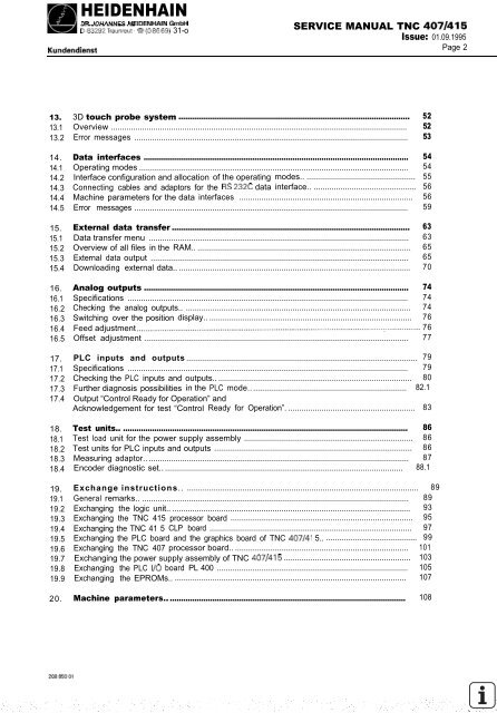
13. 3D touch probe system ........................................................................................................ 52<br />
13.1 Overview ..................................................................................................................................... 52<br />
13.2 Error messages ........................................................................................................................... 53<br />
14. Data interfaces ....................................................................................................................... 54<br />
14.1 Operating modes......................................................................................................................... 54<br />
14.2 Interface configuration and allocation of the operating modes................................................... 55<br />
14.3 Connecting cables and adaptors for the RS 23X data interface.. .............................................. 56<br />
14.4 Machine parameters for the data interfaces .............................................................................. 56<br />
14.5 Error messages ........................................................................................................................... 59<br />
15. External data transfer ........................................................................................................... 63<br />
15.1 Data transfer menu ..................................................................................................................... 63<br />
15.2 Overview of all files in the RAM.................................................................................................. 65<br />
15.3 External data output .................................................................................................................... 65<br />
15.4 Downloading external data.......................................................................................................... 70<br />
16. Analog outputs ....................................................................................................................... 74<br />
16.1 Specifications .............................................................................................................................. 74<br />
16.2 Checking the analog outputs.. ..................................................................................................... 74<br />
16.3 Switching over the position display............................................................................................. 76<br />
16.4 Feed adjustment ........................................................................................................................... 76<br />
16.5 Offset adjustment ....................................................................................................................... 77<br />
17.<br />
17.1<br />
17.2<br />
17.3<br />
17.4<br />
PLC inputs and outputs........................................................................................................ 79<br />
Specifications .............................................................................................................................. 79<br />
Checking the PLC inputs and outputs......................................................................................... 80<br />
Further diagnosis possibilities in the PLC mode.......................................................................<br />
Output “Control Ready for Operation” and<br />
82.1<br />
Acknowledgement for test “Control Ready for Operation”.......................................................... 83<br />
18. Test units.. ................................................................................................................................ 86<br />
18.1 Test load unit for the power supply assembly ............................................................................ 86<br />
18.2 Test units for PLC inputs and outputs ......................................................................................... 86<br />
18.3 Measuring adaptor....................................................................................................................... 87<br />
18.4 Encoder diagnostic set............................................................................................................. 88.1<br />
19. Exchangeinstructions.......................................................................................................... 89<br />
19.1 General remarks.......................................................................................................................... 89<br />
19.2 Exchanging the logic unit............................................................................................................. 93<br />
19.3 Exchanging the <strong>TNC</strong> <strong>415</strong> processor board .................................................................................. 95<br />
19.4 Exchanging the <strong>TNC</strong> 41 5 CLP board ........................................................................................... 97<br />
19.5 Exchanging the PLC board and the graphics board of <strong>TNC</strong> <strong>407</strong>/41 5........................................... 99<br />
19.6 Exchanging the <strong>TNC</strong> <strong>407</strong> processor board................................................................................ 101<br />
19.7 Exchanging the power supply assembly of <strong>TNC</strong> <strong>407</strong>/<strong>415</strong> ......................................................... 103<br />
19.8 Exchanging the PLC I/O board PL 400 ...................................................................................... 105<br />
19.9 Exchanging the EPROMs.. ........................................................................................................ 107<br />
20. Machine parameters............................................................................................................ 108


