

Service Manual TNC 407 / TNC 415 - heidenhain - DR. JOHANNES ...
Service Manual TNC 407 / TNC 415 - heidenhain - DR. JOHANNES ...
Service Manual TNC 407 / TNC 415 - heidenhain - DR. JOHANNES ...

Create successful ePaper yourself
Turn your PDF publications into a flip-book with our unique Google optimized e-Paper software.
Kundendienst<br />
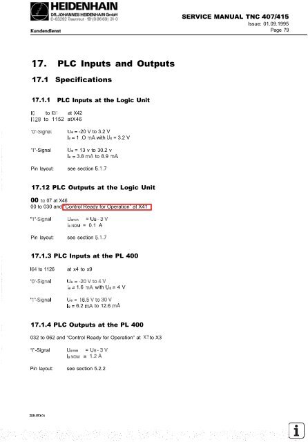
‘17. PLC Inputs and Outputs<br />
17.1 Specifications<br />
17.1.1 PLC Inputs at the Logic Unit<br />
IO to 131 at X42<br />
1128 to 1152 atX46<br />
“0’‘-Signal Ue = -20 V to 3.2 V<br />
le = 1 .O mA with Ue = 3.2 V<br />
“I’‘-Signal Ue = 13 v to 30.2 v<br />
le = 3.8 mA to 8.9 mA<br />
Pin layout: see section 5.1.7<br />
17.12 PLC Outputs at the Logic Unit<br />
00 to 07 at X46<br />
00 to 030 and “Control Ready for Operation” at X41<br />
“I”-Signal U.min = UB-3v<br />
I~NOM = 0.1 A<br />
Pin layout: see section 5.1.7<br />
17.1.3 PLC Inputs at the PL 400<br />
I64 to 1126 at x4 to x9<br />
“0’‘-Signal Ue=-20vto4v<br />
le = 1.6 mA with Ue = 4 V<br />
“I”-Signal Ue= 16.5Vto30V<br />
le = 6.2 mA to 12.6 mA<br />
17.1.4 PLC Outputs at the PL 400<br />
032 to 062 and “Control Ready for Operation” at Xl to X3<br />
“I’‘-Signal IJaM = UB-3v<br />
lawm = 1.2A<br />
Pin layout: see section 5.2.2<br />
SERVICE MANUAL <strong>TNC</strong> <strong>407</strong>/<strong>415</strong><br />
Issue: 01.09.1995<br />
Page 79


