- Page 1 and 2: Service Manual TNC 407/415 10/00 Ku
- Page 3 and 4: Contents Service Manual TNC 407/415
- Page 5 and 6: Kundendienst HEIDENHAIN DR JOHANNES
- Page 7 and 8: Kundendienst HEIDENHAIN DR JOHANNES
- Page 9 and 10: HEIDENHAIN DR JOHMlNES HEIDENHAIN G
- Page 11 and 12: Kundendienst Notes: HEIDENHAIN DR J
- Page 13 and 14: Kundendienst HEIDENHAIN DR JOHANNES
- Page 15 and 16: HEIDENHAIN DR JOHPINNES HEIDENHAIN
- Page 17 and 18: Kundendienst HEIDENHAIN DR .lclHANN
- Page 19 and 20: Kundendienst HEIDENHAIN 4.3 Hardwar
- Page 21: Kundendienst HElbENHAlN DR JOHANNES
- Page 24 and 25: Kundendienst HEIDENHAIN X21 Data In
- Page 26 and 27: Kundendienst HEIDENHAIN DR JOHANNES
- Page 28 and 29: HEIDENHAIN DR JOHANNES HEKJENHAIN G
- Page 30 and 31: Kundendienst HEIDENHAIN DR JOH~NNES
- Page 32 and 33: Kundendienst HEIDENHAIN DR JOHAPJNE
- Page 34 and 35: HEIDENHAIN DR JOHANNES HElDENHAlN G
- Page 36 and 37: HEIDENHAIN 5.4.3 Connector Designat
- Page 38 and 39: i I :r .: -! I I ! -.-- .--.-. Kund
- Page 40 and 41: HEIDENHAIN 8.2 Power Supply of the
- Page 42 and 43: Kundendienst HEIDENHAIN DR .lOHANNE
- Page 44 and 45: Kundendienst HEIDENHAIN DR .lOHANNE
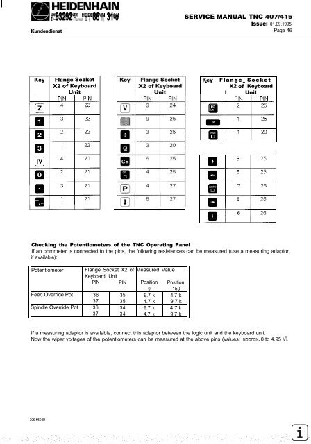
- Page 46 and 47: Kundendienst HEIDENHAIN DR JCIHANNE
- Page 48 and 49: Kundendienst HEDENHAIN DR JOHANNES
- Page 50 and 51: Kundendienst HEIDENHAIN DR JlmANNES
- Page 54 and 55: Kundendienst HEIDENHAIN DR JOHANNES
- Page 56 and 57: Kundendienst HEIDENHAIN DR .JOHANNE
- Page 58 and 59: Kundendienst HEIDENHAIN DR JOHANNES
- Page 60 and 61: Kundendienst HEIDENHAIN DR JOHANNES
- Page 62 and 63: Kundendienst HEIDENHAIN DR JOHANNES
- Page 64 and 65: Kundendienst HEIDENHAIN DR JJHANNES
- Page 66 and 67: Kundendienst SERVICE MANUAL TNC 407
- Page 68 and 69: Kundendienst HEIDENHAIN DR JOHPINNE
- Page 70 and 71: HEIDENHAIN DR .JOHANNES HEIDENHAIN
- Page 72 and 73: Kundendienst HEIDENHAIN DR JOHANNES
- Page 74 and 75: Kundendienst HEIDENHAIN 14.5.5 Erro
- Page 76 and 77: Kundendienst HEIDENHAIN cm .lOHANNE
- Page 78 and 79: HEIDENHAIN SERVICE MANUAL TNC 407/4
- Page 80 and 81: SERVICE MANUAL TNC 407/415 Issue: 0
- Page 82 and 83: Kundendienst HEIDENHAIN DR JOMNNES
- Page 84 and 85: SERVICE MANUAL TNC 407/415 Issue: 0
- Page 86 and 87: Kundendienst If the error message 1
- Page 88 and 89: Kundendienst HEIDENHAIN DR JOHANNES
- Page 90 and 91: Kundendienst HEIDENHAIN DR .mHANNES
- Page 92 and 93: Kundendienst 16.3 Switching Over th
- Page 94 and 95: II HEIDENHAIN DR .JOHmwlES HUDENHAI
- Page 96 and 97: Kundendienst HEIDENHAIN DR JOHANNES
- Page 98 and 99: Kundendienst HEIDENHAIN DR JOHANNES
- Page 100 and 101: Kundendienst HEIDENHAIN DR JOH~~NNE
- Page 102 and 103:
HEDENHAIN SERVICE MANUAL TNC 407/41
- Page 104 and 105:
L!!! HEDENHAIN DR JOHANNES HEIDENHA
- Page 106 and 107:
HEIDENHAIN Service SERVICE MANUAL T
- Page 108 and 109:
Kundendienst 19. 19.1 19.1.1 HEDENH
- Page 110 and 111:
Kundendienst HEIDENHAIN DR JOHANNES
- Page 112 and 113:
I F!!! HEIDENHAIN m I”” Ymc.m
- Page 114 and 115:
Kundendienst HEIDENHAIN DR JOHANNES
- Page 116 and 117:
Kundendienst HEIDENHAIN e) Loosen/r
- Page 118 and 119:
HEIDENHAIN DR JOHANNES HEIDENHAIN G
- Page 120 and 121:
Kundendienst HEIDENHAIN DRJOHANNES
- Page 122 and 123:
F!!!! HEIDENHAIN - DR JOHANNES HEID
- Page 124 and 125:
HEIDENHAIN d) Loosen the mounting s
- Page 126 and 127:
Kundendienst HEIDENHAIN DR .JOH~MlE
- Page 128 and 129:
Kundendienst HEIDENHAIN DR JOHANNES
- Page 130 and 131:
Code Numbers 123 MACHINE PARAMETER
- Page 132 and 133:
Function MP A B C D E F Input AE-6
- Page 134 and 135:
Function MP A B C D E F Input AE-6
- Page 136 and 137:
Function MP A B C D E F Input AE-6
- Page 138 and 139:
Function MP A B C D E F Input AE-6
- Page 140 and 141:
Function MP A B C D E F Input AE-6
- Page 142 and 143:
Function MP A B C D E F Input AE-6
- Page 144 and 145:
Function MP A B C D E F Input AE-6
- Page 146 and 147:
Function MP A B C D E F Input AE-6
- Page 148 and 149:
Function MP A B C D E F Input AE-6
- Page 150 and 151:
Function MP A B C D E F Input AE-6
- Page 152 and 153:
Function MP A B C D E F Input AE-6
- Page 154 and 155:
Integral PLC Function MP A B C D E
- Page 156 and 157:
Function MP A B C D E F Input AE-6
- Page 158 and 159:
Function MP A B C D E F Input AE-6
- Page 160 and 161:
Function MP A B C D E F Input AE-6
- Page 162 and 163:
Function MP A B C D E F Input AE-6
- Page 164 and 165:
Function MP A B C D E F Input AE-6
- Page 166 and 167:
Digitizing with 3D-Touch Probe Func
- Page 168 and 169:
Function MP A B C D E F Input AE-6
- Page 170 and 171:
Display and Programming Function MP
- Page 172 and 173:
Function MP A B C D E F Input AE-6
- Page 174 and 175:
Function MP A B C D E F Input AE-6
- Page 176 and 177:
Function MP A B C D E F Input AE-6
- Page 178 and 179:
Colours, General Display and FK-Gra
- Page 180 and 181:
User Parameters Function MP A B C D
- Page 182 and 183:
Function MP A B C D E F Input AE-6
- Page 184 and 185:
Machining and Program Run Function
- Page 186 and 187:
Function MP A B C D E F Input AE-6
- Page 188 and 189:
Function MP A B C D E F Input AE-6
- Page 190 and 191:
Hardware Function MP A B C D E F In
- Page 192 and 193:
Function MP A B C D E F Input AE-6
- Page 194 and 195:
Function MP A B C D E F Input AE-6