- Page 1:
ModuleWare Reference Manualfor the
- Page 4 and 5:
Table of ContentsGated OR (or1) . .
- Page 6:
Table of ContentsBufif0 Primitive (
- Page 9 and 10:
List of TablesTable 5-18. N-Way Spl
- Page 11 and 12:
List of TablesTable 7-20. RS Flip-F
- Page 14 and 15:
List of TablesTable 10-41. XNOR Pri
- Page 16 and 17:
IntroductionNaming ConventionsNamin
- Page 18 and 19:
IntroductionSupported VHDL Packages
- Page 20 and 21:
IntroductionReset/Clear BehaviorYou
- Page 22 and 23:
IntroductionSet/Preset BehaviorSet/
- Page 24 and 25:
IntroductionGate BehaviorFunctioncl
- Page 26 and 27:
IntroductionEnable/Load BehaviorFun
- Page 28 and 29:
IntroductionVHDL Coding StyleNotes
- Page 30 and 31:
IntroductionDesign Rule CheckingFor
- Page 32 and 33:
IntroductionSlice SupportOtherwise
- Page 34 and 35:
Logic PartsN-Input AND Gate (and)N-
- Page 36 and 37:
Logic PartsN-Input XOR Gate (xor)N-
- Page 38 and 39:
Logic PartsN-Input NOR Gate (nor)N-
- Page 40 and 41:
Logic PartsAssign (assignment)Assig
- Page 42 and 43:
Logic PartsBit Setter (bitset)suffi
- Page 44 and 45:
Logic PartsBus Driver (busdrive)Bus
- Page 46 and 47:
Logic PartsGated OR (or1)Gated OR (
- Page 48 and 49:
Logic PartsInverter (inv)Inverter (
- Page 50 and 51:
Logic PartsReduction OR (tor)Reduct
- Page 52 and 53:
Logic PartsThree-state Buffer (trib
- Page 54 and 55:
Logic PartsThree-state bus (tribus)
- Page 56 and 57:
Logic PartsVariable Width N-Input A
- Page 58 and 59:
Logic PartsVariable Width N-Input X
- Page 60 and 61:
ConstantsConstant Value (constval)C
- Page 62 and 63:
ConstantsPower (vdd)Power (vdd)This
- Page 64 and 65:
Combinatorial PartsDecoder, Separat
- Page 66 and 67:
Combinatorial PartsDecoder, Separat
- Page 68 and 69:
Combinatorial PartsDecoder, Combine
- Page 70 and 71:
Combinatorial PartsEncoder (encoder
- Page 72 and 73:
Combinatorial PartsN-Input Multiple
- Page 74 and 75:
Combinatorial PartsN-Input One-hot
- Page 76 and 77:
Combinatorial PartsN-Input One-hot
- Page 78 and 79:
Combinatorial PartsW-Bit Multiplexe
- Page 80 and 81:
Combinatorial PartsW-Bit Multiplexe
- Page 82 and 83:
Bit Manipulation PartsN-Bus Merge (
- Page 84 and 85:
Bit Manipulation PartsN-Bus Merge (
- Page 86 and 87:
Bit Manipulation PartsN-Way Splitte
- Page 88 and 89:
Bit Manipulation PartsN-Way Splitte
- Page 90 and 91:
Bit Manipulation PartsBus Fill (wor
- Page 92 and 93:
Bit Manipulation PartsFixed Bit Sel
- Page 94 and 95:
Bit Manipulation PartsFixed Shifter
- Page 96 and 97:
Bit Manipulation PartsFixed Shifter
- Page 98 and 99:
Arithmetic Parts181 ALU (alu181)181
- Page 100 and 101:
Arithmetic Parts181 ALU (alu181)ovf
- Page 102 and 103:
Arithmetic PartsAbsolute Value (abs
- Page 104 and 105:
Arithmetic PartsAccumulator (acc)ad
- Page 106 and 107:
Arithmetic PartsAdder (add)Adder (a
- Page 108 and 109:
Arithmetic PartsAdder (add)Table 6-
- Page 110 and 111:
Arithmetic PartsAdder Subtractor (a
- Page 112 and 113:
Arithmetic PartsAdder Subtractor (a
- Page 114 and 115:
Arithmetic PartsComparator (cmp)Com
- Page 116 and 117:
Arithmetic PartsDecrementer (dec)De
- Page 118 and 119:
Arithmetic PartsIncrementer (inc)In
- Page 120 and 121:
Arithmetic PartsIncrementer Decreme
- Page 122 and 123:
Arithmetic PartsIncrementer Decreme
- Page 124 and 125:
Arithmetic PartsLeft Shifter (lshif
- Page 126 and 127:
Arithmetic PartsMultiplier (mult)A
- Page 128 and 129:
Arithmetic PartsRight Shifter (rshi
- Page 130 and 131:
Arithmetic PartsSubtractor (sub)Sub
- Page 132 and 133:
Arithmetic PartsSubtractor (sub)Tab
- Page 134 and 135:
Arithmetic PartsUni-function Compar
- Page 136 and 137:
Arithmetic PartsVariable Shifter (v
- Page 138 and 139: Arithmetic PartsVariable Shifter (v
- Page 140 and 141: Register PartsD Flip-Flop (adff)D F
- Page 142 and 143: Register PartsD Flip-Flop (adff)Par
- Page 144 and 145: Register PartsD Latch (dlatch)If lo
- Page 146 and 147: Register PartsD Latch (dlatch)Table
- Page 148 and 149: Register PartsJK Flip-Flop (jkff)Fu
- Page 150 and 151: Register PartsJK Latch (jklatch)JK
- Page 152 and 153: Register PartsJK Latch (jklatch)Asy
- Page 154 and 155: Register PartsRS Flip-Flop (rsff)RS
- Page 156 and 157: Register PartsRS Flip-Flop (rsff)Ta
- Page 158 and 159: Register PartsRS Latch (rslatch)Fun
- Page 160 and 161: Register PartsRS Latch (rslatch)Syn
- Page 162 and 163: Register PartsT Flip-Flop (tff)Func
- Page 164 and 165: Register PartsT Latch (tlatch)T Lat
- Page 166 and 167: Register PartsT Latch (tlatch)Async
- Page 168 and 169: Register PartsT Latch (tlatch)168Mo
- Page 170 and 171: Sequential PartsBank of Flip-Flops
- Page 172 and 173: Sequential PartsBank of Flip-Flops
- Page 174 and 175: Sequential PartsBank of Latches (la
- Page 176 and 177: Sequential PartsClock Divider (clkd
- Page 178 and 179: Sequential PartsConfigurable Counte
- Page 180 and 181: Sequential PartsConfigurable Counte
- Page 182 and 183: Sequential PartsConfigurable Counte
- Page 184 and 185: Sequential PartsConfigurable Counte
- Page 186 and 187: Sequential PartsConfigurable Counte
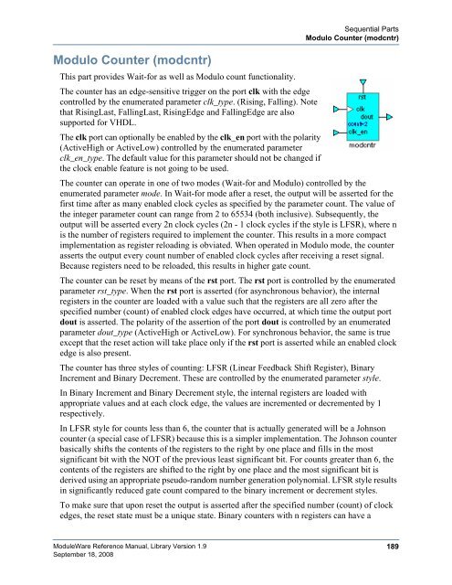
- Page 190 and 191: Sequential PartsModulo Counter (mod
- Page 192 and 193: Sequential PartsModulo Counter (mod
- Page 194 and 195: Sequential PartsModulo Counter (mod
- Page 196 and 197: Sequential PartsParallel to Serial
- Page 198 and 199: Sequential PartsParallel to Serial
- Page 200 and 201: Sequential PartsSerial to Parallel
- Page 202 and 203: Sequential PartsThree-state Bank of
- Page 204 and 205: Sequential PartsThree-state Bank of
- Page 206 and 207: Memory PartsDual Port RAM (ram2p)Du
- Page 208 and 209: Memory PartsFirst In First Out (fif
- Page 210 and 211: Memory PartsFirst In First Out (fif
- Page 212 and 213: Memory PartsSingle Port RAM (ram)Si
- Page 214 and 215: Memory PartsRegister File (regfile)
- Page 216 and 217: Memory PartsROM (rom)ROM (rom)This
- Page 218 and 219: Memory PartsROM (rom)The correspond
- Page 220 and 221: Memory PartsROM (rom)Extended segme
- Page 222 and 223: Memory PartsStack (stack)The reset
- Page 224 and 225: Memory PartsStack (stack)Parameters
- Page 226 and 227: Memory PartsSynthesizable Dual-Port
- Page 228 and 229: Memory PartsSynthesizable Single-Po
- Page 230 and 231: Primitive PartsIntroductionIntroduc
- Page 232 and 233: Primitive PartsIntroductionTable 10
- Page 234 and 235: Primitive PartsBuffer Primitive (pb
- Page 236 and 237: Primitive PartsBufif0 Primitive (pb
- Page 238 and 239:
Primitive PartsBufif1 Primitive (pb
- Page 240 and 241:
Primitive PartsCMOS Primitive (pcmo
- Page 242 and 243:
Primitive PartsNAND Primitive (pnan
- Page 244 and 245:
Primitive PartsNOR Primitive (pnor)
- Page 246 and 247:
Primitive PartsNOT Primitive (pnot)
- Page 248 and 249:
Primitive PartsNotif0 Primitive (pn
- Page 250 and 251:
Primitive PartsNotif1 Primitive (pn
- Page 252 and 253:
Primitive PartsPMOS Primitive (ppmo
- Page 254 and 255:
Primitive PartsPullup Primitive (pp
- Page 256 and 257:
Primitive PartsRCMOS Primitive (prc
- Page 258 and 259:
Primitive PartsRPMOS Primitive (prp
- Page 260 and 261:
Primitive PartsXNOR Primitive (pxno
- Page 262 and 263:
Stimulus PartsSimple Clock (clk)Sim
- Page 264 and 265:
Stimulus PartsCompound Clock (cmpdc
- Page 266 and 267:
Stimulus PartsPulse (pulse)Pulse (p
- Page 268 and 269:
Stimulus PartsConstant Wave (constw
- Page 270 and 271:
Stimulus PartsRandom Value (random)
- Page 272 and 273:
Stimulus PartsRandom Value (random)
- Page 274 and 275:
Stimulus PartsCounter Value (counte
- Page 276 and 277:
Stimulus PartsCounter Value (counte
- Page 278 and 279:
Name ListName Description Pagedlatc
- Page 280 and 281:
Name ListName Description Pagesplit
- Page 282 and 283:
Function ListFunction Description P
- Page 284 and 285:
Function ListFunction Description P
- Page 286 and 287:
Function List286ModuleWare Referenc
- Page 288 and 289:
A BC D E F G H I J K L M N O P Q R
- Page 290 and 291:
A BC D E F G H I J K L M N O P Q R
- Page 292 and 293:
4. RESTRICTIONS ON USE. You may cop
- Page 294:
15. CONTROLLING LAW, JURISDICTION A