- Page 1 and 2:
Engineering Standards The City of F
- Page 3 and 4:
Engineering Standards Table of Cont
- Page 5 and 6:
Engineering Standards SECTION 6 LAN
- Page 7 and 8:
Engineering Standards SECTION 1 - G
- Page 9 and 10:
Engineering Standards 1.03 Enforcem
- Page 11 and 12:
Engineering Standards C. Section 3
- Page 13 and 14:
Engineering Standards direct respon
- Page 15 and 16:
Engineering Standards D. Abandonmen
- Page 17 and 18:
Engineering Standards SECTION 2 - T
- Page 19 and 20:
Engineering Standards B. Roadway Ge
- Page 21 and 22:
Engineering Standards TABLE 2.1: Ge
- Page 23 and 24:
Engineering Standards Major Thoroug
- Page 25 and 26:
Engineering Standards TABLE 2.2: Mi
- Page 27 and 28:
Engineering Standards 5. Type A-A,
- Page 29 and 30:
Engineering Standards B. Roadway Ge
- Page 31 and 32:
Engineering Standards TABLE 2.1: Ge
- Page 33 and 34:
Engineering Standards Major Thoroug
- Page 35 and 36:
Engineering Standards TABLE 2.2: Mi
- Page 37 and 38:
Engineering Standards 5. Type A-A,
- Page 39 and 40:
Engineering Standards The ROW width
- Page 41 and 42:
Engineering Standards the approach
- Page 43 and 44:
Engineering Standards (600’) meas
- Page 45 and 46:
Engineering Standards b. A Type G r
- Page 47 and 48:
Engineering Standards c. Minimum st
- Page 49 and 50:
Engineering Standards Type A or B 1
- Page 51 and 52:
Engineering Standards Storage Lengt
- Page 53 and 54:
Engineering Standards D. Minimum De
- Page 55 and 56:
Engineering Standards Cross Street
- Page 57 and 58:
Engineering Standards 18' ROW 12' 1
- Page 59 and 60:
Engineering Standards I. Alley Grad
- Page 61 and 62:
Engineering Standards 9. Differenti
- Page 63 and 64:
Engineering Standards Criteria Driv
- Page 65 and 66:
Engineering Standards H. Driveways
- Page 67 and 68:
Engineering Standards 100' ROW 15'
- Page 69 and 70:
Engineering Standards thoroughfares
- Page 71 and 72:
Engineering Standards 46' - 0" 10'
- Page 73 and 74:
Engineering Standards B. Corner Vis
- Page 75 and 76:
Engineering Standards 4. Sight Line
- Page 77 and 78:
Engineering Standards 2.09 Traffic
- Page 79 and 80:
Engineering Standards 8. Street lig
- Page 81 and 82: Engineering Standards E. The follow
- Page 83 and 84: Engineering Standards the Director
- Page 85 and 86: Engineering Standards Institute of
- Page 87 and 88: Engineering Standards 2. The sectio
- Page 89 and 90: Engineering Standards SECTION 3 - P
- Page 91 and 92: Engineering Standards B. The subgra
- Page 93 and 94: Engineering Standards 2. PVR-TxDOT
- Page 95 and 96: Engineering Standards Section 3 - P
- Page 97 and 98: Engineering Standards Table 3.1 - P
- Page 99 and 100: Engineering Standards Section 4 - D
- Page 101 and 102: Engineering Standards Table 4.2 She
- Page 103 and 104: Engineering Standards 4. Coincident
- Page 105 and 106: Engineering Standards Figure 1: Dow
- Page 107 and 108: Engineering Standards 2. The City r
- Page 109 and 110: Engineering Standards S n S e = Roa
- Page 111 and 112: Engineering Standards 4. An emergen
- Page 113 and 114: Engineering Standards F. The Inlet
- Page 115 and 116: Engineering Standards • Column 37
- Page 117 and 118: Engineering Standards 2. Laterals s
- Page 119 and 120: Engineering Standards FIGURE 3 Stor
- Page 121 and 122: Engineering Standards • Column 18
- Page 123 and 124: Engineering Standards facility as p
- Page 125 and 126: Engineering Standards Water feature
- Page 127 and 128: Engineering Standards B. Supercriti
- Page 129 and 130: Engineering Standards Section 4 - D
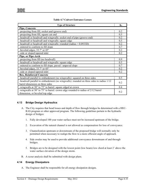
- Page 131: Engineering Standards 4.12 Hydrauli
- Page 135 and 136: Engineering Standards submittal as
- Page 137 and 138: Engineering Standards Detention/Ret
- Page 139 and 140: Engineering Standards SECTION 5 - W
- Page 141 and 142: Engineering Standards 5.1.3 Separat
- Page 143 and 144: Engineering Standards 3. PVC water
- Page 145 and 146: Engineering Standards F. Fire hydra
- Page 147 and 148: Engineering Standards 5.2 Wastewate
- Page 149 and 150: Engineering Standards Under each sc
- Page 151 and 152: Engineering Standards G. All mains
- Page 153 and 154: Engineering Standards J. Pumps shal
- Page 155 and 156: Engineering Standards 5.4 Easements
- Page 157 and 158: Engineering Standards 3. Tunneling
- Page 159 and 160: Engineering Standards Conditions Re
- Page 161 and 162: Engineering Standards Section 6 - L
- Page 163 and 164: Engineering Standards FIGURE 6.2: C
- Page 165 and 166: Engineering Standards Section 7 - I
- Page 167 and 168: Engineering Standards SECTION 8 - E
- Page 169 and 170: Engineering Standards 8.03 Texas Co
- Page 171 and 172: Engineering Standards C. Temporary
- Page 173 and 174: Engineering Standards SECTION 9 - S
- Page 175 and 176: Engineering Standards protection ag
- Page 177 and 178: Engineering Standards c. Major stre
- Page 179 and 180: Engineering Standards 1. Height. An
- Page 181 and 182: Engineering Standards 1. Geometry (
- Page 183 and 184:
Engineering Standards b. Cast-in-pl
- Page 185 and 186:
Engineering Standards 13. E. Gravit
- Page 187 and 188:
Engineering Standards SECTION 10 -
- Page 189 and 190:
Engineering Standards The City requ
- Page 191 and 192:
Engineering Standards GN - General
- Page 193 and 194:
Engineering Standards verified to m
- Page 195 and 196:
Engineering Standards General Notes
- Page 197 and 198:
TS TECHNICAL SPECIFICATIONS TS - Te
- Page 199 and 200:
321123 Sand Bedding May 2012 321126
- Page 201 and 202:
SECTION 015813 PROJECT SIGN PART 1
- Page 203 and 204:
SECTION 017416 DUST CONTROL PART 1
- Page 205 and 206:
PART 2 - PRODUCTS Not used PART 3 -
- Page 207 and 208:
SECTION 032200 WELDED WIRE FABRIC P
- Page 209 and 210:
SECTION 033101 DRILLED SHAFT FOUNDA
- Page 211 and 212:
PART 1 - GENERAL 1.01 DESCRIPTION S
- Page 213 and 214:
SECTION 034100 CONCRETE STRUCTURES
- Page 215 and 216:
SECTION 071300 MOISTURE BARRIER PAR
- Page 217 and 218:
approved by the city. In any case,
- Page 219 and 220:
E. The service enclosure shall be m
- Page 221 and 222:
C. The assembly will contain either
- Page 223 and 224:
SECTION 265620 LUMINAIRE FIXTURE PA
- Page 225 and 226:
SECTION 270500 CONDUIT PART 1 - GEN
- Page 227 and 228:
PART 4 - MEASUREMENT AND PAYMENT 4.
- Page 229 and 230:
4.02 PAYMENT the revised quantity.
- Page 231 and 232:
SECTION 312323 SELECT FILL PART 1 -
- Page 233 and 234:
4.02 PAYMENT by the Contractor, the
- Page 235 and 236:
PART 3 - EXECUTION 3.01 INSTALLATIO
- Page 237 and 238:
SECTION 313600 GABIONS AND GABION M
- Page 239 and 240:
SECTION 321112 MOISTURE TREATED SUB
- Page 241 and 242:
SECTION 321113 LIME TREATMENT PART
- Page 243 and 244:
PART 3 - EXECUTION 3.01 EQUIPMENT T
- Page 245 and 246:
Minimum passing 3/4" sieve: Minimum
- Page 247 and 248:
inch and not more than 1.0 inch fro
- Page 249 and 250:
PART 1 - GENERAL 1.01 DESCRIPTION S
- Page 251 and 252:
SECTION 321126 ASPHALT BASE COURSE
- Page 253 and 254:
SECTION 321216 HOT MIX ASPHALT PAVE
- Page 255 and 256:
PART 3 - EXECUTION 3.01 INSTALLATIO
- Page 257 and 258:
PART 3 - EXECUTION 3.01 PREPARATION
- Page 259 and 260:
SECTION 321400 CONCRETE PAVERS PART
- Page 261 and 262:
SECTION 321645 DRIVEWAY APPROACH PA
- Page 263 and 264:
4.02 PAYMENT A. All work performed
- Page 265 and 266:
4.02 PAYMENT A. All work performed
- Page 267 and 268:
4.02 PAYMENT A. All work performed
- Page 269 and 270:
SECTION 321723 PAVEMENT MARKERS AND
- Page 271 and 272:
PART 4 - MEASUREMENT AND PAYMENT 4.
- Page 273 and 274:
PART 3 - EXECUTION 3.01 INSTALLATIO
- Page 275 and 276:
3.03 WARRANTY REQUIREMENTS A. Each
- Page 277 and 278:
SECTION 328000 IRRIGATION SYSTEM PA
- Page 279 and 280:
GUARANTEE FOR LANDSCAPE IRRIGATION
- Page 281 and 282:
2.03 PIPE FITTINGS: A. PVC Sch. 40,
- Page 283 and 284:
B. Quick Coupling Valves: 1. 10 in
- Page 285 and 286:
B. Mainline and Lateral Piping: Ins
- Page 287 and 288:
PART 4 -MEASUREMENT AND PAYMENT 4.0
- Page 289 and 290:
SECTION 329119 TOPSOIL PART 1 - GEN
- Page 291 and 292:
2.02 FERTILIZER inch. Sod shall be
- Page 293 and 294:
3.04 PLANTING: receive subsequent a
- Page 295 and 296:
SECTION 329300 TREE, SHRUB, AND GRO
- Page 297 and 298:
3. Alternate to B&B: Plants grown i
- Page 299 and 300:
3.09 CLEANUP All excess soil, soil
- Page 301 and 302:
SECTION 329600 REMOVAL, PROTECTION
- Page 303 and 304:
SECTION 330131 WASTEWATER AND MANHO
- Page 305 and 306:
PART 1 - GENERAL 1.01 DESCRIPTION S
- Page 307 and 308:
B. Refer to Public Works Constructi
- Page 309 and 310:
A. Shop drawings of the casing pipe
- Page 311 and 312:
Ventilation system shall provide a
- Page 313 and 314:
B. Section 331240 - Polyethylene En
- Page 315 and 316:
5. Apply a thin film of the lubrica
- Page 317 and 318:
SECTION 331114 PVC PIPE FOR WATER D
- Page 319 and 320:
PART 4 - MEASUREMENT AND PAYMENT 4.
- Page 321 and 322:
B. A tapping saddle shall be used t
- Page 323 and 324:
SECTION 331217 RESILIENT SEATED GAT
- Page 325 and 326:
SECTION 331218 BUTTERFLY VALVES PAR
- Page 327 and 328:
SECTION 331219 FIRE HYDRANTS PART 1
- Page 329 and 330:
SECTION 331240 POLYETHYLENE ENCASEM
- Page 331 and 332:
PART 1 - GENERAL 1.01 DESCRIPTION S
- Page 333 and 334:
PART 1 - GENERAL 1.01 DESCRIPTION S
- Page 335 and 336:
E. All residential wastewater later
- Page 337 and 338:
PART 3 - EXECUTION 3.01 CONSTRUCTIO
- Page 339 and 340:
C. Appurtenances shall be construct
- Page 341 and 342:
E. No connecting wastewater main sh
- Page 343 and 344:
PART 4 - MEASUREMENT AND PAYMENT 4.
- Page 345 and 346:
PART 4 - MEASUREMENT AND PAYMENT 4.
- Page 347 and 348:
D. Manholes deeper that fifteen fee
- Page 349 and 350:
SECTION 334113 REINFORCED CONCRETE
- Page 351 and 352:
SECTION 334200 REINFORCED BOX CULVE
- Page 353 and 354:
SECTION 334914 HEADWALLS AND WINGWA
- Page 355 and 356:
PART 1 - GENERAL 1.01 DESCRIPTION S
- Page 357 and 358:
C. All traffic signal mast arm pole
- Page 359 and 360:
PART 4 - MEASUREMENT AND PAYMENT 4.
- Page 361 and 362:
PART 4 - MEASUREMENT AND PAYMENT 4.
- Page 363 and 364:
SECTION 344135 GROUND BOX PART 1 -
- Page 365 and 366:
SECTION 344140 TEMPORARY TRAFFIC SI
- Page 367 and 368:
PART 4 - MEASUREMENT AND PAYMENT 4.
- Page 369 and 370:
F. If, at any time during construct
- Page 371 and 372:
AM APPROVED MATERIALS LIST AM - App
- Page 373 and 374:
City of Frisco Approved Materials L
- Page 375 and 376:
City of Frisco Approved Materials L
- Page 377 and 378:
City of Frisco Approved Materials L
- Page 379 and 380:
City of Frisco Approved Materials L
- Page 381 and 382:
City of Frisco Approved Materials L
- Page 383 and 384:
City of Frisco Approved Materials L
- Page 385 and 386:
Common Name Dwarf Crape Myrtle City
- Page 387 and 388:
SD STANDARD CONSTRUCTION DETAILS SD
- Page 389 and 390:
D05 Recessed Curb Inlet - Sheet 2 o
- Page 391 and 392:
City Logo (See Note #1) City of Fri
- Page 393 and 394:
STANDARD CONSTRUCTION DETAIL THOROU
- Page 395 and 396:
STANDARD CONSTRUCTION DETAIL EXISTI
- Page 397 and 398:
OPTION 1 OPTION 2 STANDARD CONSTRUC
- Page 399 and 400:
STREET HEADER AT EXISTING PAVEMENT
- Page 401 and 402:
PLAN SECTION A-A SECTION B-B STANDA
- Page 403 and 404:
PLAN SECTION A-A STANDARD CONSTRUCT
- Page 405 and 406:
PLAN SECTION A-A STANDARD CONSTRUCT
- Page 407 and 408:
PLAN SECTION A-A SECTION B-B JOINT
- Page 409 and 410:
OPPOSING TRAFFIC GORE DETAIL NEUTRA
- Page 411 and 412:
TYPICAL INSTALLATION STANDARD CONST
- Page 413 and 414:
STANDARD CONSTRUCTION DETAIL STREET
- Page 415 and 416:
PLAN PROFILE STANDARD CONSTRUCTION
- Page 417 and 418:
PLAN PROFILE STANDARD CONSTRUCTION
- Page 419 and 420:
INLET SECTION FOR RECESSED AND STAN
- Page 421 and 422:
CLASS "B" STANDARD CONSTRUCTION DET
- Page 423 and 424:
CLASS "B-1" STANDARD CONSTRUCTION D
- Page 425 and 426:
CLASS "G" STANDARD CONSTRUCTION DET
- Page 427 and 428:
STANDARD CONSTRUCTION DETAIL INFILT
- Page 429 and 430:
PLAN SECTION X-X STANDARD CONSTRUCT
- Page 431 and 432:
STANDARD CONSTRUCTION DETAIL HORIZO
- Page 433 and 434:
STANDARD CONSTRUCTION DETAIL THRUST
- Page 435 and 436:
STANDARD CONSTRUCTION DETAIL BUTTER
- Page 437 and 438:
” ” ” STANDARD CONSTRUCTION D
- Page 439 and 440:
STANDARD CONSTRUCTION DETAILS FIRE
- Page 441 and 442:
STANDARD CONSTRUCTION DETAIL RESIDE
- Page 443 and 444:
PLAN VIEW SECTION STANDARD CONSTRUC
- Page 445 and 446:
PLAN VIEW SECTION STANDARD CONSTRUC
- Page 447 and 448:
ELEVATION FIELD INSTALLATION DETAIL
- Page 449 and 450:
STANDARD CONSTRUCTION DETAIL PRECAS
- Page 451 and 452:
STANDARD CONSTRUCTION DETAIL VENTED
- Page 453 and 454:
STANDARD CONSTRUCTION DETAIL MANHOL
- Page 455 and 456:
PLAN VIEW INSTALLATION AND REMOVAL
- Page 457 and 458:
PROFILE VIEW SECTION X-X STANDARD C
- Page 459 and 460:
ELEVATION FIELD INSTALLATION DETAIL
- Page 461 and 462:
PLAN SECTION STANDARD CONSTRUCTION
- Page 463 and 464:
PLAN SECTION STANDARD CONSTRUCTION
- Page 465 and 466:
STANDARD CONSTRUCTION DETAIL CONCRE
- Page 467 and 468:
Engineering Standards APPENDIX A DE
- Page 469 and 470:
Engineering Standards Equal: Materi
- Page 471 and 472:
Engineering Standards LF LL LLDPE L