

Microseismic Monitoring and Geomechanical Modelling of CO2 - bris
Microseismic Monitoring and Geomechanical Modelling of CO2 - bris
Microseismic Monitoring and Geomechanical Modelling of CO2 - bris

You also want an ePaper? Increase the reach of your titles
YUMPU automatically turns print PDFs into web optimized ePapers that Google loves.
5.3. NUMERICAL MODELLING<br />
5.3.1 Fluid-flow simulation<br />
Any attempt to model geomechanical deformation <strong>of</strong> hydrocarbon reservoirs must begin by modelling<br />
the movement <strong>of</strong> fluid, the properties <strong>of</strong> the fluids, <strong>and</strong> the changes in pore pressure. Fortunately,<br />
such problems have long been <strong>of</strong> interest to the hydrocarbon industry, <strong>and</strong> so a range <strong>of</strong> commercial<br />
fluid-flow simulators are available. Most have good records <strong>of</strong> reliability for dealing with reservoir fluid<br />
flow processes. All are similar <strong>and</strong> can in theory be coupled to geomechanical simulators. Throughout<br />
this work I will be using MORE as the fluid-flow simulator, because <strong>of</strong> the ease with which it can be<br />
coupled using a bespoke Message Passing Interface (MPI) developed as part <strong>of</strong> the IPEGG project.<br />
5.3.2 <strong>Geomechanical</strong> modelling<br />
In order to model the geomechanical deformation, I use a finite element code, ELFEN, developed<br />
by Swansea University <strong>and</strong> Rockfield Ltd.<br />
ELFEN uses a CamClay constitutive model - this is<br />
described in detail by Crook et al. (2006) <strong>and</strong> is summarised below. In the elastic regime, the material<br />
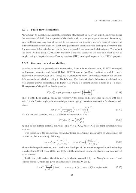
deformation is modelled according to Hooke’s law. The limits <strong>of</strong> elastic behaviour are defined by a<br />
yield surface (shown schematically in Figure 5.3) which is a smooth surface defined in p − q space.<br />
The equation <strong>of</strong> the yield surface is given by<br />
F (σ, ε p v) = g(θ, p)q + (p − p t ) tan β<br />
( p − pc<br />
p t − p c<br />
) 1/n<br />
, (5.11)<br />
where θ is the Lode angle, p t <strong>and</strong> p c are respectively the tensile <strong>and</strong> compressive intersects with the p<br />
axis, β is the friction angle, n is a material parameter. g(θ, p) describes a correction for the deviatoric<br />
plane,<br />
(<br />
g(θ, p) =<br />
1<br />
1 − β π (p)<br />
(1 + β π (p) r3<br />
q 3 )) N<br />
π<br />
N π is a material constant, <strong>and</strong> β π is defined as a function <strong>of</strong> p as<br />
( )<br />
β π (p) = β0 π exp β1 π p p0 c<br />
p c<br />
(5.12)<br />
(5.13)<br />
β π 0 <strong>and</strong> β π 1 are further material constants, <strong>and</strong> r 3 = 27J ′ 3/2, where J ′ 3 is the third deviatoric stress<br />
invariant.<br />
The evolution <strong>of</strong> the yield surface (strain hardening or s<strong>of</strong>tening) is computed as a function <strong>of</strong> the<br />
volumetric plastic strain, ε p v, following<br />
p c = p 0 c exp<br />
( vε<br />
p<br />
v<br />
(λ − κ)<br />
)<br />
, p t = p 0 t exp<br />
( ) v(ε<br />
p<br />
v ) max<br />
, (5.14)<br />
(λ − κ)<br />
where v is the specific volume, <strong>and</strong> λ <strong>and</strong> κ are the slopes <strong>of</strong> the normal compression <strong>and</strong> unloadingreloading<br />
lines (Crook et al., 2006), <strong>and</strong> (ε p v) max is the maximum volumetric plastic strain encountered<br />
by an element.<br />
Inside the yield surface the deformation is elastic, controlled by the Young’s modulus E <strong>and</strong><br />
Poisson’s ratio ν, which are given as a function <strong>of</strong> porosity, Φ <strong>and</strong> p,<br />
( ) e p + A<br />
E = E 0 (Φ) c , ν = ν min + (ν max − ν min )(1 − exp(−mp)). (5.15)<br />
B<br />
87


