

Microseismic Monitoring and Geomechanical Modelling of CO2 - bris
Microseismic Monitoring and Geomechanical Modelling of CO2 - bris
Microseismic Monitoring and Geomechanical Modelling of CO2 - bris

You also want an ePaper? Increase the reach of your titles
YUMPU automatically turns print PDFs into web optimized ePapers that Google loves.
CHAPTER 5.<br />
GEOMECHANICAL SIMULATION OF CO 2 INJECTION<br />
2700<br />
6<br />
2700<br />
6<br />
2750<br />
4<br />
2750<br />
4<br />
2800<br />
2<br />
2800<br />
2<br />
2850<br />
0<br />
2850<br />
0<br />
Depth (m)<br />
2900<br />
2950<br />
3000<br />
−2<br />
−4<br />
−6<br />
Depth (m)<br />
2900<br />
2950<br />
3000<br />
−2<br />
−4<br />
−6<br />
3050<br />
3100<br />
−8<br />
3050<br />
3100<br />
−8<br />
3150<br />
−10<br />
3150<br />
−10<br />
0 100 200 300 400 500<br />
X (m)<br />
−12<br />
0 1000 2000 3000 4000 5000<br />
X (m)<br />
−12<br />
(a)<br />
(b)<br />
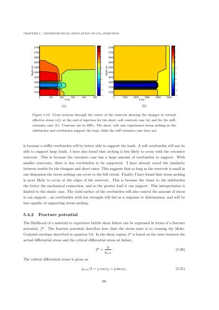
Figure 5.12: Cross sections through the centre <strong>of</strong> the reservoir showing the changes in vertical<br />
effective stress (σ ′ 3) at the end <strong>of</strong> injection for the short, s<strong>of</strong>t reservoir case (a) <strong>and</strong> for the stiff,<br />
extensive case (b). Contours are in MPa. The short, s<strong>of</strong>t case experiences stress arching as the<br />
sideburden <strong>and</strong> overburden support the load, while the stiff extensive case does not.<br />
is because a stiffer overburden will be better able to support the loads. A s<strong>of</strong>t overburden will not be<br />
able to support large loads. I have also found that arching is less likely to occur with the extensive<br />
reservoir. This is because the extensive case has a large amount <strong>of</strong> overburden to support. With<br />
smaller reservoirs, there is less overburden to be supported. I have already noted the similarity<br />
between results for the elongate <strong>and</strong> short cases. This suggests that so long as the reservoir is small in<br />
one dimension the stress arching can occur to the full extent. Finally, I have found that stress arching<br />
is more likely to occur at the edges <strong>of</strong> the reservoir. This is because the closer to the sideburden<br />
the better the mechanical connection, <strong>and</strong> so the greater load it can support. This interpretation is<br />
limited to the elastic case. The yield surface <strong>of</strong> the overburden will also control the amount <strong>of</strong> stress<br />
is can support - an overburden with low strength will fail as a response to deformation, <strong>and</strong> will be<br />
less capable <strong>of</strong> supporting stress arching.<br />
5.4.2 Fracture potential<br />
The likelihood <strong>of</strong> a material to experience brittle shear failure can be expressed in terms <strong>of</strong> a fracture<br />
potential, f p . The fracture potential describes how close the stress state is to crossing the Mohr-<br />
Coulomb envelope described in equation 5.6. In the shear regime f p is based on the ratio between the<br />
actual differential stress <strong>and</strong> the critical differential stress at failure,<br />
The critical differential stress is given as<br />
f p =<br />
q<br />
q crit<br />
. (5.20)<br />
q crit /2 = χ cos ϕ f + p sin ϕ f , (5.21)<br />
98


