Microseismic Monitoring and Geomechanical Modelling of CO2 - bris
Microseismic Monitoring and Geomechanical Modelling of CO2 - bris
Microseismic Monitoring and Geomechanical Modelling of CO2 - bris
Create successful ePaper yourself
Turn your PDF publications into a flip-book with our unique Google optimized e-Paper software.
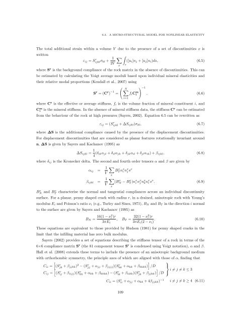
6.3. A MICRO-STRUCTURAL MODEL FOR NONLINEAR ELASTICITY<br />
The total additional strain within a volume V due to the presence <strong>of</strong> a set <strong>of</strong> discontinuities x is<br />
written<br />
ε ij = S r ijklσ kl + 1<br />
2V<br />
∑<br />
∫<br />
([u i ]n j + [u j ]n i )ds, (6.5)<br />
x<br />
where S r is the background compliance <strong>of</strong> the rock matrix in the absence <strong>of</strong> discontinuities. This can<br />
be estimated by calculating the Voigt average moduli based upon individual mineral elasticities <strong>and</strong><br />
their relative modal proportions (Kendall et al., 2007) using<br />
( N<br />
) −1<br />
∑<br />
S r = (C r ) −1 = f i C m i , (6.6)<br />
where C r is the effective or average stiffness, f i is the volume fraction <strong>of</strong> mineral constituent i, <strong>and</strong><br />
C m i<br />
s<br />
i=1<br />
is the mineral stiffness. In the absence <strong>of</strong> mineral stiffness data, the stiffness C r can be estimated<br />
from the behaviour <strong>of</strong> the rock at high pressures (Sayers, 2002). Equation 6.5 can be rewritten as<br />
ε ij = (S r ijkl + ∆S ijkl )σ kl , (6.7)<br />
where ∆S is the additional compliance caused by the presence <strong>of</strong> the displacement discontinuities.<br />
For displacement discontinuities that are considered as planar features rotationally invariant around<br />
n, ∆S is given by Sayers <strong>and</strong> Kachanov (1995) as<br />
∆S ijkl = 1 4 (δ ikα jl + δ il α jk + δ jk α il + δ jl α ik ) + β ijkl , (6.8)<br />
where δ ij is the Kronecker delta. The second <strong>and</strong> fourth order tensors α <strong>and</strong> β are given by<br />
α ij = 1 ∑<br />
BT x n x i n x j s x<br />
V<br />
x<br />
β ijkl = 1 ∑<br />
(BN x − BT x )n x i n x j n x<br />
V<br />
kn x l s x . (6.9)<br />
x<br />
BN x <strong>and</strong> Bx T characterise the normal <strong>and</strong> tangential compliances across an individual discontinuity<br />
surface. For a planar, penny shaped crack with radius r, in a drained, anisotropic rock with Young’s<br />
modulus E i <strong>and</strong> Poisson’s ratio ν i (e.g., Turley <strong>and</strong> Sines, 1971), B N <strong>and</strong> B T in the direction i normal<br />
to the surface are given by Sayers <strong>and</strong> Kachanov (1995) as<br />
B N = 16(1 − ν2 i )r<br />
3πE i<br />
, B T = 32(1 − ν2 i )r<br />
3πE i (2 − ν i ) . (6.10)<br />
These equations are equivalent to those provided by Hudson (1981) for penny shaped cracks in the<br />
limit that the infilling material has zero bulk modulus.<br />
Sayers (2002) provides a set <strong>of</strong> equations describing the stiffness tensor <strong>of</strong> a rock in terms <strong>of</strong> the<br />
6×6 compliance matrix S r (the 81 component tensor S r is condensed using Voigt notation), α <strong>and</strong> β.<br />
Hall et al. (2008) extends these terms to include the presence <strong>of</strong> an anisotropic background medium<br />
with orthorhombic symmetry, the principle axes <strong>of</strong> which are aligned with those <strong>of</strong> α, finding that<br />
[<br />
] ⎫<br />
C ii = (Sjk r + β jjkk) 2 − (Sjj r + α jj + β jjjj )(Skk r + α kk + β kkkk ) /D ⎬<br />
[<br />
]<br />
C ij = (Sij r + β iijj)(Skk r + α kk + β kkkk ) − (Sik r + β iikk)(Sjk r + β jjkk) /D ⎭ i ≠ j ≠ k ≤ 3<br />
C ii = (S r ii + α jj + α kk + 4β jjkk ) −1 i ≠ j ≠ k ≥ 4 (6.11)<br />
109


