

Microseismic Monitoring and Geomechanical Modelling of CO2 - bris
Microseismic Monitoring and Geomechanical Modelling of CO2 - bris
Microseismic Monitoring and Geomechanical Modelling of CO2 - bris

Create successful ePaper yourself
Turn your PDF publications into a flip-book with our unique Google optimized e-Paper software.
5.4. RESULTS<br />
0<br />
500<br />
1000<br />
Depth (m)<br />
1500<br />
2000<br />
2500<br />
3000<br />
Reservoir<br />
Overburden<br />
3500<br />
0 0.1 0.2 0.3 0.4 0.5<br />
Porosity<br />
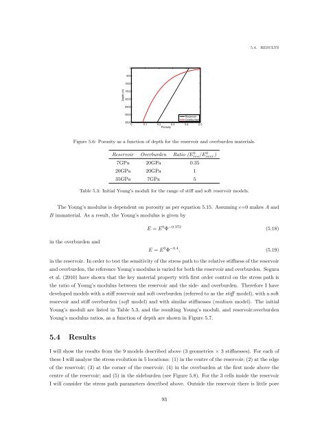
Figure 5.6: Porosity as a function <strong>of</strong> depth for the reservoir <strong>and</strong> overburden materials.<br />
Reservoir Overburden Ratio (Eres/E 0 over)<br />
0<br />
7GPa 20GPa 0.35<br />
20GPa 20GPa 1<br />
35GPa 7GPa 5<br />
Table 5.3: Initial Young’s moduli for the range <strong>of</strong> stiff <strong>and</strong> s<strong>of</strong>t reservoir models.<br />
The Young’s modulus is dependent on porosity as per equation 5.15. Assuming e=0 makes A <strong>and</strong><br />
B immaterial. As a result, the Young’s modulus is given by<br />
E = E 0 Φ −0.372 (5.18)<br />
in the overburden <strong>and</strong><br />
E = E 0 Φ −0.4 , (5.19)<br />
in the reservoir. In order to test the sensitivity <strong>of</strong> the stress path to the relative stiffness <strong>of</strong> the reservoir<br />
<strong>and</strong> overburden, the reference Young’s modulus is varied for both the reservoir <strong>and</strong> overburden. Segura<br />
et al. (2010) have shown that the key material property with first order control on the stress path is<br />
the ratio <strong>of</strong> Young’s modulus between the reservoir <strong>and</strong> the side- <strong>and</strong> overburden. Therefore I have<br />
developed models with a stiff reservoir <strong>and</strong> s<strong>of</strong>t overburden (referred to as the stiff model), with a s<strong>of</strong>t<br />
reservoir <strong>and</strong> stiff overburden (s<strong>of</strong>t model) <strong>and</strong> with similar stiffnesses (medium model). The initial<br />
Young’s moduli are listed in Table 5.3, <strong>and</strong> the resulting Young’s moduli, <strong>and</strong> reservoir:overburden<br />
Young’s modulus ratios, as a function <strong>of</strong> depth are shown in Figure 5.7.<br />
5.4 Results<br />
I will show the results from the 9 models described above (3 geometries × 3 stiffnesses). For each <strong>of</strong><br />
these I will analyse the stress evolution in 5 locations: (1) in the centre <strong>of</strong> the reservoir; (2) at the edge<br />
<strong>of</strong> the reservoir; (3) at the corner <strong>of</strong> the reservoir; (4) in the overburden at the first node above the<br />
centre <strong>of</strong> the reservoir; <strong>and</strong> (5) in the sideburden (see Figure 5.8). For the 3 cells inside the reservoir<br />
I will consider the stress path parameters described above. Outside the reservoir there is little pore<br />
93


