

Microseismic Monitoring and Geomechanical Modelling of CO2 - bris
Microseismic Monitoring and Geomechanical Modelling of CO2 - bris
Microseismic Monitoring and Geomechanical Modelling of CO2 - bris

You also want an ePaper? Increase the reach of your titles
YUMPU automatically turns print PDFs into web optimized ePapers that Google loves.
5.4. RESULTS<br />
Overburden<br />
Extension in the overburden<br />
Side<br />
burden<br />
Reservoir is contracting<br />
Compression<br />
in the side<br />
burden<br />
(a)<br />
Overburden<br />
Compression in the overburden<br />
Side<br />
burden<br />
Reservoir is inflating<br />
Extension<br />
in the side<br />
burden<br />
(b)<br />
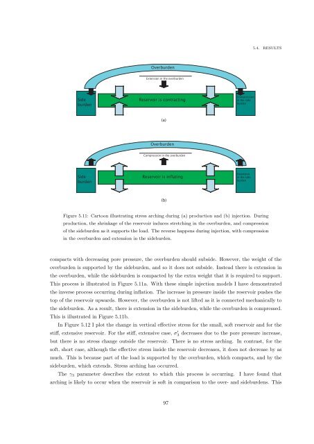
Figure 5.11: Cartoon illustrating stress arching during (a) production <strong>and</strong> (b) injection. During<br />
production, the shrinkage <strong>of</strong> the reservoir induces stretching in the overburden, <strong>and</strong> compression<br />
<strong>of</strong> the sideburden as it supports the load. The reverse happens during injection, with compression<br />
in the overburden <strong>and</strong> extension in the sideburden.<br />
compacts with decreasing pore pressure, the overburden should subside. However, the weight <strong>of</strong> the<br />
overburden is supported by the sideburden, <strong>and</strong> so it does not subside. Instead there is extension in<br />
the overburden, while the sideburden is compacted by the extra weight that it is required to support.<br />
This process is illustrated in Figure 5.11a. With these simple injection models I have demonstrated<br />
the inverse process occurring during inflation. The increase in pressure inside the reservoir pushes the<br />
top <strong>of</strong> the reservoir upwards. However, the overburden is not lifted as it is connected mechanically to<br />
the sideburden. As a result, there is extension in the sideburden, while the overburden is compressed.<br />
This is illustrated in Figure 5.11b.<br />
In Figure 5.12 I plot the change in vertical effective stress for the small, s<strong>of</strong>t reservoir <strong>and</strong> for the<br />
stiff, extensive reservoir. For the stiff, extensive case, σ ′ 3 decreases due to the pore pressure increase,<br />
but there is no stress change outside the reservoir. There is no stress arching. In contrast, for the<br />
s<strong>of</strong>t, short case, although the effective stress inside the reservoir decreases, it does not decrease by as<br />
much. This is because part <strong>of</strong> the load is supported by the overburden, which compacts, <strong>and</strong> by the<br />
sideburden, which extends. Stress arching has occurred.<br />
The γ 3 parameter describes the extent to which this process is occurring. I have found that<br />
arching is likely to occur when the reservoir is s<strong>of</strong>t in comparison to the over- <strong>and</strong> sideburdens. This<br />
97


