

Microseismic Monitoring and Geomechanical Modelling of CO2 - bris
Microseismic Monitoring and Geomechanical Modelling of CO2 - bris
Microseismic Monitoring and Geomechanical Modelling of CO2 - bris

You also want an ePaper? Increase the reach of your titles
YUMPU automatically turns print PDFs into web optimized ePapers that Google loves.
CHAPTER 4. A COMPARISON OF MICROSEISMIC MONITORING OF FRACTURE STIMULATION DUE TO WATER<br />
VERSUS CO 2 INJECTION<br />
0.2<br />
0.0<br />
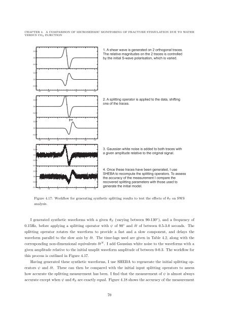
1. A shear wave is generated on 2 orthogonal traces.<br />
The relative magnitudes on the 2 traces is controlled<br />
by the initial S-wave polarisation, which is varied.<br />
-0.2<br />
0.2<br />
0.0<br />
-0.2<br />
-15 -10 -5 0 5 10 15<br />
0.2<br />
0.0<br />
2. A splitting operator is applied to the data, shifting<br />
one <strong>of</strong> the traces.<br />
-0.2<br />
0.2<br />
0.0<br />
-0.2<br />
-15 -10 -5 0 5 10 15<br />
0.2<br />
0.0<br />
3. Gaussian white noise is added to both traces with<br />
a given amplitude relative to the original signal.<br />
-0.2<br />
-0.4<br />
0.2<br />
0.0<br />
-0.2<br />
-0.4<br />
-15 -10 -5 0 5 10 15<br />
4. Once these traces have been generated, I use<br />
SHEBA to recompute the splitting operators. To assess<br />
the accuracy <strong>of</strong> the measurement I compare the<br />
recovered splitting parameters with those used to<br />
generate the initial model.<br />
Figure 4.17: Workflow for generating synthetic splitting results to test the effects <strong>of</strong> θ S on SWS<br />
analysis.<br />
I generated synthetic waveforms with a given θ S (varying between 90-130 ◦ ), <strong>and</strong> a frequency <strong>of</strong><br />
0.15Hz, before applying a splitting operator with ψ <strong>of</strong> 90 ◦ <strong>and</strong> δt <strong>of</strong> between 0.5-3.0 seconds. The<br />
splitting operator rotates the waveform to provide a fast <strong>and</strong> a slow component, <strong>and</strong> delays the<br />
waveform parallel to the slow axis by δt. The time-lags used are given in Table 4.2, along with the<br />
corresponding non-dimensional equivalents δt N . I add Gaussian white noise to the waveforms with a<br />
given amplitude relative to the initial unsplit waveform amplitude <strong>of</strong> between 0-0.3. The workflow for<br />
this process is outlined in Figure 4.17.<br />
Having generated these synthetic waveforms, I use SHEBA to regenerate the initial splitting operators<br />
ψ <strong>and</strong> δt. These can then be compared with the initial input splitting operators to assess<br />
how accurate the splitting measurement has been. I find that the measurement <strong>of</strong> ψ is almost always<br />
accurate except when ψ <strong>and</strong> θ S are exactly equal. Figure 4.18 shows the accuracy <strong>of</strong> the measurement<br />
70


