

Microseismic Monitoring and Geomechanical Modelling of CO2 - bris
Microseismic Monitoring and Geomechanical Modelling of CO2 - bris
Microseismic Monitoring and Geomechanical Modelling of CO2 - bris

You also want an ePaper? Increase the reach of your titles
YUMPU automatically turns print PDFs into web optimized ePapers that Google loves.
7.3. RESULTS FROM SIMPLE GEOMECHANICAL MODELS<br />
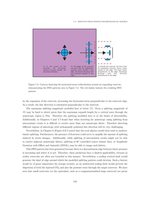
1.) In the center <strong>of</strong> the<br />
reservoir, the horizontal<br />
stresses increase equally. No<br />
anisotropy develops.<br />
2.) The edges <strong>of</strong> the reservoir<br />
can push into the sideburden,<br />
opening cracks parallel to the<br />
edge. Anisotropy develops with<br />
fast direction parallel to the<br />
edge.<br />
3.) Outside the reservoir, the force from<br />
the exp<strong>and</strong>ing reservoir closes cracks<br />
parallel to the edge. This leave cracks<br />
perpendicular to the edge. Anisotropy<br />
develops with fast direction<br />
perpendicular to the edge.<br />
Figure 7.3: Cartoon depicting the horizontal stress redistribution around an exp<strong>and</strong>ing reservoir,<br />
demonstrating the SWS patterns seen in Figure 7.2. The red dashes indicate the resulting SWS<br />
pattern.<br />
by the expansion <strong>of</strong> the reservoir, increasing the horizontal stress perpendicular to the reservoir edge.<br />
As a result, the fast direction is orientated perpendicular to the reservoir.<br />
The maximum splitting magnitude modelled here is below 1%. Even a splitting magnitude <strong>of</strong><br />
1% may be hard to detect given that the maximum raypath length for a vertical wave through the<br />
anisotropic region is 75m. Therefore the splitting modelled here is at the limits <strong>of</strong> detectability.<br />
Additionally, in Chapters 3 <strong>and</strong> 4 I found that when inverting for anisotropy using splitting from<br />
microseismic events it is difficult to resolve more than one anisotropic fabric. Therefore detecting<br />
different regions <strong>of</strong> anisotropy with orthogonally polarised fast direction will be very challenging.<br />
Nevertheless, in Chapter 6 (Figure 6.9) I noted that the rock physics model does tend to underestimate<br />
splitting. Furthermore, the presence <strong>of</strong> fractures could serve to amplify the amount <strong>of</strong> splitting<br />
induced by stress changes. Additionally, while splitting <strong>of</strong> microseismic events might not be able<br />
to resolve adjacent anisotropic fabrics, splitting <strong>of</strong> 9C controlled source seismic data, or Amplitude<br />
Variation with Offset <strong>and</strong> Azimuth (AVOA), may be able to image such fabrics.<br />
This SWS pattern has been generated because there is a discontinuous edge between where pressure<br />
is increasing <strong>and</strong> where it is not. Therefore, these prediction have a limited applicability, because in<br />
reality reservoirs are <strong>of</strong>ten not bounded in this manner. Nevertheless, a sealing vertical fault would<br />
generate the kind <strong>of</strong> edge around which the modelled splitting pattern could develop. Such a feature<br />
would be <strong>of</strong> great importance for storage security, as an undetected sealing fault would prevent the<br />
dispersion <strong>of</strong> both the injected CO 2 <strong>and</strong> also the pressure wave through the target reservoir. We have<br />
seen that small reservoirs (or the equivalent, such as a compartmentalised large reservoir) are prone<br />
143


