del freddo La caldaia ® - Olimpia Splendid
del freddo La caldaia ® - Olimpia Splendid
del freddo La caldaia ® - Olimpia Splendid

Create successful ePaper yourself
Turn your PDF publications into a flip-book with our unique Google optimized e-Paper software.
12<br />
2.2.2<br />
I<br />
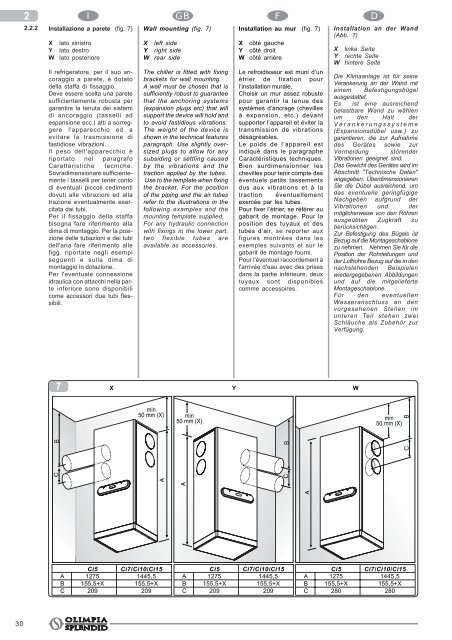
Installazione a parete (fig. 7)<br />
X<br />
Y<br />
W<br />
lato sinistro<br />
lato destro<br />
lato posteriore<br />
Il refrigeratore, per il suo ancoraggio<br />
a parete, è dotato<br />
<strong>del</strong>la staffa di fissaggio.<br />
Deve essere scelta una parete<br />
sufficientemente robusta per<br />
garantire la tenuta dei sistemi<br />
di ancoraggio (tasselli ad<br />
espansione ecc.) atti a sorreggere<br />
l'apparecchio ed a<br />
evitare la trasmissione di<br />
fastidiose vibrazioni.<br />
Il peso <strong>del</strong>l'apparecchio è<br />
riportato nel paragrafo<br />
Caratteristiche tecniche.<br />
Sovradimensionare sufficientemente<br />
i tasselli per tener conto<br />
di eventuali piccoli cedimenti<br />
dovuti alle vibrazioni ed alla<br />
trazione eventualmente esercitata<br />
dai tubi.<br />
Per il fissaggio <strong>del</strong>la staffa<br />
bisogna fare riferimento alla<br />
dima di montaggio. Per la posizione<br />
<strong>del</strong>le tubazioni e dei tubi<br />
<strong>del</strong>l'aria fare riferimento alle<br />
figg. riportate negli esempi<br />
seguenti e sulla dima di<br />
montaggio in dotazione.<br />
Per l'eventuale connessione<br />
idraulica con attacchi nella parte<br />
inferiore sono disponibili<br />
come accessori due tubi flessibili.<br />
GB F D<br />
Wall mounting (fig. 7)<br />
X<br />
Y<br />
W<br />
left side<br />
right side<br />
rear side<br />
The chiller is fitted with fixing<br />
brackets for wall mounting.<br />
A wall must be chosen that is<br />
sufficiently robust to guarantee<br />
that the anchoring systems<br />
(expansion plugs etc) that will<br />
support the device will hold and<br />
to avoid fastidious vibrations.<br />
The weight of the device is<br />
shown in the technical features<br />
paragraph. Use slightly oversized<br />
plugs to allow for any<br />
subsiding or settling caused<br />
by the vibrations and the<br />
traction applied by the tubes.<br />
Use to the template when fixing<br />
the bracket. For the position<br />
of the piping and the air tubes<br />
refer to the illustrations in the<br />
following examples and the<br />
mounting template supplied.<br />
For any hydraulic connection<br />
with fixings in the lower part,<br />
two flexible tubes are<br />
available as accessories.<br />
Installation au mur (fig. 7)<br />
X côté gauche<br />
Y côté droit<br />
W côté arrière<br />
Le refroidisseur est muni d’un<br />
étrier de fixation pour<br />
l’installation murale.<br />
Choisir un mur assez robuste<br />
pour garantir la tenue des<br />
systèmes d’ancrage (chevilles<br />
à expansion, etc.) devant<br />
supporter l’appareil et éviter la<br />
transmission de vibrations<br />
désagréables.<br />
Le poids de l’appareil est<br />
indiqué dans le paragraphe<br />
Caractéristiques techniques.<br />
Bien surdimensionner les<br />
chevilles pour tenir compte des<br />
éventuels petits tassements<br />
dus aux vibrations et à la<br />
traction éventuellement<br />
exercée par les tubes.<br />
Pour fixer l’étrier, se référer au<br />
gabarit de montage. Pour la<br />
position des tuyaux et des<br />
tubes d’air, se reporter aux<br />
figures montrées dans les<br />
exemples suivants et sur le<br />
gabarit de montage fourni.<br />
Pour l'éventuel raccordement à<br />
l'arrivée d'eau avec des prises<br />
dans la partie inférieure, deux<br />
tuyaux sont disponibles<br />
comme accessoires.<br />
Installation an der Wand<br />
(Abb. 7)<br />
X<br />
Y<br />
W<br />
linke Seite<br />
rechte Seite<br />
hintere Seite<br />
Die Klimaanlage ist für seine<br />
Verankerung an der Wand mit<br />
einem Befestigungsbügel<br />
ausgestattet.<br />
Es ist eine ausreichend<br />
belastbare Wand zu wählen<br />
um den Halt der<br />
Verankerungssysteme<br />
(Expansionsdübel usw.) zu<br />
garantieren, die zur Aufnahme<br />
des Gerätes sowie zur<br />
Vermeidung störender<br />
Vibrationen geeignet sind.<br />
Das Gewicht des Gerätes wird im<br />
Abschnitt "Technische Daten"<br />
angegeben. Überdimensionieren<br />
Sie die Dübel ausreichend, um<br />
das eventuelle geringfügige<br />
Nachgeben aufgrund der<br />
Vibrationen und der<br />
möglicherweise von den Rohren<br />
ausgeübten Zugkraft zu<br />
berücksichtigen.<br />
Zur Befestigung des Bügels ist<br />
Bezug auf die Montageschablone<br />
zu nehmen. Nehmen Sie für die<br />
Position der Rohrleitungen und<br />
der Luftrohre Bezug auf die in den<br />
nachstehenden Beispielen<br />
wiedergegebenen Abbildungen<br />
und auf die mitgelieferte<br />
Montageschablone.<br />
Für den eventuellen<br />
Wasseranschluss an den<br />
vorgesehenen Stellen im<br />
unteren Teil stehen zwei<br />
Schläuche als Zubehör zur<br />
Verfügung.<br />
7<br />
X<br />
Y<br />
W<br />
min<br />
50 mm (X)<br />
min<br />
50 mm (X)<br />
min<br />
50 mm (X)<br />
A<br />
A<br />
A<br />
C<br />
C B<br />
C<br />
B<br />
B<br />
Ci5 Ci7/Ci10/Ci15<br />
A 1275 1445,5<br />
B 155,5+X 155,5+X<br />
C 209 209<br />
Ci5 Ci7/Ci10/Ci15<br />
A 1275 1445,5<br />
B 155,5+X 155,5+X<br />
C 209 209<br />
Ci5 Ci7/Ci10/Ci15<br />
A 1275 1445,5<br />
B 155,5+X 155,5+X<br />
C 280 280<br />
30