

1948-1952 Shop Service Manual - - Hudson-Essex-Terraplane Club
1948-1952 Shop Service Manual - - Hudson-Essex-Terraplane Club
1948-1952 Shop Service Manual - - Hudson-Essex-Terraplane Club

Create successful ePaper yourself
Turn your PDF publications into a flip-book with our unique Google optimized e-Paper software.
6 - 26 ELECTRICAL SYSTEM<br />
7. Turn the condenser switch to the " Micro-farad". The<br />
meter should read 20 to 25 microfarads for both six and<br />
eight cylinder engines.<br />
8. Turn the condenser switch to the "Meg-ohm" position.<br />
Meter should now read in the blue bar at left side<br />
marked "MEG" for satisfactory condenser insulation.<br />
If the meter reads in the red bar or over to the extreme<br />
right, replace the condenser.<br />
NOTE: When making the above checks, the condenser<br />
should be at operating temperatures.<br />
COIL<br />
The ignition coil used is Auto-Lite CR-6012-A; the coil<br />
provides a means of stepping up the six volt primary current<br />
to high voltage necessary to jump the spark plug gap. The<br />
primary winding of the coil is connected to the battery<br />
through the distributor contact points. The secondary winding<br />
of the coil is connected to the spark plug through the<br />
rotor and distributor cap.<br />
COIL TEST:<br />
1. Calibrate Coil Breaker Unit.<br />
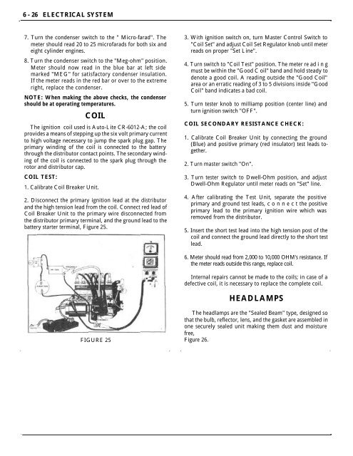
2. Disconnect the primary ignition lead at the distributor<br />
and the high tension lead from the coil. Connect red lead of<br />
Coil Breaker Unit to the primary wire disconnected from<br />
the distributor primary terminal, and the ground lead to the<br />
battery starter terminal, Figure 25.<br />
3. With ignition switch on, turn Master Control Switch to<br />
"Coil Set" and adjust Coil Set Regulator knob until meter<br />
reads on proper "Set Line".<br />
4. Turn switch to "Coil Test" position. The meter re ad i n g<br />
must be within the "Good C oil" band and hold steady to<br />
denote a good coil. A reading outside the "Good Coil"<br />
area or an erratic reading of 3 to 5 divisions inside "Good<br />
Coil" band indicates a bad coil.<br />
5. Turn tester knob to milliamp position (center line) and<br />
turn ignition switch "OFF".<br />
COIL SECONDARY RESISTANCE CHECK:<br />
1. Calibrate Coil Breaker Unit by connecting the ground<br />
(Blue) and positive primary (red insulator) test leads together.<br />
2. Turn master switch "On".<br />
3. Turn tester switch to Dwell-Ohm position, and adjust<br />
Dwell-Ohm Regulator until meter reads on "Set" line.<br />
4. After calibrating the Test Unit, separate the positive<br />
primary and ground test leads, c o n n e c t the positive<br />
primary lead to the primary ignition wire which was<br />
removed from the distributor.<br />
5. Insert the short test lead into the high tension post of the<br />
coil and connect the ground lead directly to the short test<br />
lead.<br />
6. Meter should read from 2,000 to 10,000 OHM's resistance. If<br />
the meter reads outside this range, replace coil.<br />
Internal repairs cannot be made to the coils; in case of a<br />
defective coil, it is necessary to replace the complete coil.<br />
HEADLAMPS<br />
FIGURE 25<br />
The headlamps are the "Sealed Beam" type, designed so<br />
that the bulb, reflector, lens, and the gasket are assembled in<br />
one securely sealed unit making them dust and moisture<br />
free,<br />
Figure 26.


