- Page 1 and 2: HUDSON SHOP SERVICE MANUAL 1948 - 1
- Page 3 and 4: FORWARD I The information contained
- Page 5 and 6: ALPHABETICAL INDEX - CONTINUED III
- Page 7 and 8: ALPHABETICAL INDEX - CONTINUED V Gr
- Page 9 and 10: ALPHABETICAL INDEX - CONTINUED VII
- Page 11 and 12: LUBRICATION 1 - 1 The present day h
- Page 13 and 14: LUBRICATION 1 - 3
- Page 15 and 16: LUBRICATION 1 - 5 WATER RESISTANT L
- Page 17 and 18: LUBRICATION 1 - 7 ENGINE OILING CIR
- Page 19 and 20: LUBRICATION 1 - 9 cylinder engines.
- Page 21 and 22: ENGINE TUNE-UP 2 - 1 SECTION 2 ENGI
- Page 23 and 24: ENGINE TUNE-UP 2 -3 If a starter-ba
- Page 25 and 26: ENGINE TUNE-UP 2 -5 5. After comple
- Page 27 and 28: ENGINE TUNE-UP 2 -7 Connect one lea
- Page 29 and 30: ENGINE TUNE-UP 2 -9 BREAKER ARM SPR
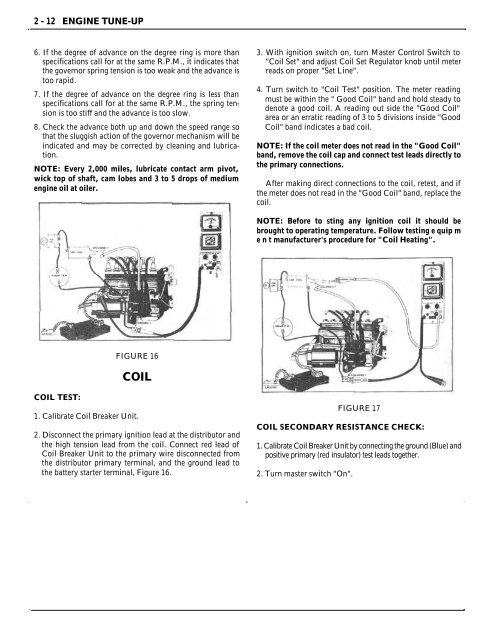
- Page 31: ENGINE TUNE-UP 2 -11 VACUUM ADVANCE
- Page 35 and 36: ENGINE TUNE-UP 2 -15 FIGURE 22 CAUT
- Page 37 and 38: ENGINE TUNE-UP 2 -17 2. Connect a s
- Page 39 and 40: ENGINE TUNE-UP 2 -19 3. Pump travel
- Page 41 and 42: ENGINE TUNE-UP 2 -21 2. Hold thrott
- Page 43 and 44: ENGINE 3 - 1 ENGINE: Arrangement Co
- Page 45 and 46: ENGINE 3 - 3 VALVES: Intake Angle o
- Page 47 and 48: ENGINE 3 - 5 LUBRICATION 8 CYLINDER
- Page 49 and 50: ENGINE TUNE-UP 3 - 7 2. Inlet conne
- Page 51 and 52: ENGINE 3 - 9 NOTE: The #2 crossmemb
- Page 53 and 54: ENGINE 3 - 11 INSPECTION: 1. Remove
- Page 55 and 56: ENGINE 3 - 13 CAUTION: If the threa
- Page 57 and 58: ENGINE 3 - 15 NOTE: When Installing
- Page 59 and 60: ENGINE 3 - 17 When assembling new o
- Page 61 and 62: ENGINE 3 - 19 CAUTION: Be sure the
- Page 63 and 64: ENGINE 3 - 21 A code letter and the
- Page 65 and 66: ENGINE 3 - 23 a 3 to 4 pound pull.
- Page 67 and 68: ENGINE 3 - 25 The connecting rod be
- Page 69 and 70: ENGINE 3 - 27 Figure 32. On the 8 c
- Page 71 and 72: FIGURE 33 ENGINE 3 - 29
- Page 73 and 74: ENGINE 3 - 31 TIMING GEAR COVER OIL
- Page 75 and 76: ENGINE 3 - 33 TIMING GEAR Installat
- Page 77 and 78: ENGINE 3 - 35 REMOVAL: CAMSHAFT (8
- Page 79 and 80: ENGINE 3 - 37 18. Replace coolant a
- Page 81 and 82: FIGURE 44 ENGINE 3 - 39
- Page 83 and 84:
ENGINE 3 - 41 Valve guides can be r
- Page 85 and 86:
SECTION 4 FUEL SYSTEM & EXHAUST CAR
- Page 87 and 88:
SECTION 4 FUEL SYSTEM & EXHAUST ENG
- Page 89 and 90:
FUEL SYSTEM & EXHAUST 4 - 5 An anti
- Page 91 and 92:
FUEL SYSTEM & EXHAUST 4 - 7 UNLOADE
- Page 93 and 94:
FUEL SYSTEM & EXHAUST 4 - 9 6. Remo
- Page 95 and 96:
FUEL SYSTEM & EXHAUST 4 - 11 5. Ins
- Page 97 and 98:
FUEL SYSTEM & EXHAUST 4 - 13 18. In
- Page 99 and 100:
FUEL SYSTEM & EXHAUST 4-15 CARBURET
- Page 101 and 102:
FUEL SYSTEM & EXHAUST 4 - 17 2. Wit
- Page 103 and 104:
FUEL SYSTEM & EXHAUST 4 - 19 6. Rem
- Page 105 and 106:
FUEL SYSTEM & EXHAUST 4 - 21 7. Ins
- Page 107 and 108:
FUEL SYSTEM & EXHAUST 4 - 23 FIGURE
- Page 109 and 110:
FUEL SYSTEM & EXHAUST 4 - 25 NOTE:
- Page 111 and 112:
TWIN CARBURETOR Installation INSTRU
- Page 113 and 114:
FUEL SYSTEM & EXHAUST 4 - 29 pipe a
- Page 115 and 116:
FUEL SYSTEM & EXHAUST 4 - 31 AIR CL
- Page 117 and 118:
FUEL SYSTEM & EXHAUST 4 - 33 FIGURE
- Page 119 and 120:
FIGURE 106 FUEL SYSTEM & EXHAUST 4
- Page 121 and 122:
FUEL SYSTEM & EXHAUST 4 - 37 4. Dri
- Page 123 and 124:
FUEL SYSTEM & EXHAUST 4 - 39 GAUGE
- Page 125 and 126:
FUEL SYSTEM & EXHAUST 4 - 41 MANIFO
- Page 127 and 128:
COOLING SYSTEM 5 - 1 SECTION 5 COOL
- Page 129 and 130:
COOLING SYSTEM 5 - 3 2. Install rad
- Page 131 and 132:
COOLING SYSTEM 5 - 5 WATER PUMP - 6
- Page 133 and 134:
COOLING SYSTEM 5 - 7 1. Cover bolt
- Page 135 and 136:
COOLING SYSTEM 5 - 9 Continue heati
- Page 137 and 138:
ELECTRICAL SYSTEM 6 - 1 Models GENE
- Page 139 and 140:
ELECTRICAL SYSTEM 6 - 3 IAT-4009 IA
- Page 141 and 142:
ELECTRICAL SYSTEM 6 - 5 a heavy shu
- Page 143 and 144:
ELECTRICAL SYSTEM 6 - 7 STARTER REM
- Page 145 and 146:
ELECTRICAL SYSTEM 6 - 9 The generat
- Page 147 and 148:
ELECTRICAL SYSTEM 6 - 11 6. Remove
- Page 149 and 150:
ELECTRICAL SYSTEM 6 - 13
- Page 151 and 152:
ELECTRICAL SYSTEM 6 - 15 BRUSH REPL
- Page 153 and 154:
ELECTRICAL SYSTEM 6 - 17 GENERATOR
- Page 155 and 156:
ELECTRICAL SYSTEM 6 - 19 3. Run eng
- Page 157 and 158:
ELECTRICAL SYSTEM 6 - 21 screw (D)
- Page 159 and 160:
ELECTRICAL SYSTEM 6 - 23 Installati
- Page 161 and 162:
ELECTRICAL SYSTEM 6 - 25 FIGURE 23
- Page 163 and 164:
ELECTRICAL SYSTEM 6 - 27 FIGURE 26
- Page 165 and 166:
ELECTRICAL SYSTEM 6 - 29 Weather Co
- Page 167 and 168:
ELECTRICAL SYSTEM 6 - 31 6. If swit
- Page 169 and 170:
CLUTCH 7 - 1 Driving Plate Diameter
- Page 171 and 172:
CLUTCH 7 - 3 DRAIN AND REFILL CLUTC
- Page 173 and 174:
CLUTCH 7 - 5 2. Loosen the propelle
- Page 175 and 176:
CLUTCH 7 - 7 ENGAGING SPRINGS If cl
- Page 177 and 178:
CLUTCH 7 - 9 3. Tighten the cap scr
- Page 179 and 180:
TRANSMISSION 8 - 1 SECTION 8 TRANSM
- Page 181 and 182:
TRANSMISSION 8 - 3 1. Gear Pilot Be
- Page 183 and 184:
TRANSMISSION 8 - 5 3. Remove govern
- Page 185 and 186:
TRANSMISSION 8 - 7 washer, and two
- Page 187 and 188:
TRANSMISSION 8 - 9 open, clean and
- Page 189 and 190:
TRANSMISSION 8 - 11 towards gear th
- Page 191 and 192:
TRANSMISSION 8 - 13 2. Place second
- Page 193 and 194:
TRANSMISSION 8 - 15 Worn, rough mai
- Page 195 and 196:
TRANSMISSION 8 - 17 NOTE: Check shi
- Page 197 and 198:
TRANSMISSION 8 - 19 SECTION 8 TRANS
- Page 199 and 200:
TRANSMISSION 8 - 21 1. Synchronizer
- Page 201 and 202:
TRANSMISSION 8 - 23 8. Make a dummy
- Page 203 and 204:
TRANSMISSION 8 - 25 center of the c
- Page 205 and 206:
TRANSMISSION 8 - 27 case, entering
- Page 207 and 208:
TRANSMISSION 8 - 29 REMOVAL AND Ins
- Page 209 and 210:
OVERDRIVE 9 - 1
- Page 211 and 212:
OVERDRIVE 9 - 3 NOTE: Unless otherw
- Page 213 and 214:
OVERDRIVE 9 - 5 speed of the latter
- Page 215 and 216:
FIGURE 10 OVERDRIVE 9 - 7
- Page 217 and 218:
OVERDRIVE 9 - 9 CONTROL SWITCH The
- Page 219 and 220:
OVERDRIVE 9 - 11 4. Remove the reta
- Page 221 and 222:
OVERDRIVE 9 - 13 Installation OF AD
- Page 223 and 224:
OVERDRIVE 9 - 15 3. Install the rin
- Page 225 and 226:
OVERDRIVE 9 - 17 8. Remove the gove
- Page 227 and 228:
OVERDRIVE 9 - 19 8. Install synchro
- Page 229 and 230:
OVERDRIVE 9 - 21 NOTE: Assemble syn
- Page 231 and 232:
OVERDRIVE 9 - 23 UNIT CHECKS OVERDR
- Page 233 and 234:
OVERDRIVE 9 - 25 4. Connect test la
- Page 235 and 236:
OVERDRIVE 9 - 27 ELECTRICAL CONDITI
- Page 237 and 238:
OVERDRIVE 9 - 29 B. Occasionally, t
- Page 239 and 240:
PROPELLER SHAFT 10 - 1 Front Shaft
- Page 241 and 242:
PROPELLER SHAFT 10 - 3 5. Tap on th
- Page 243 and 244:
REAR AXLE 11 - 1 SECTION 11 REAR AX
- Page 245 and 246:
REAR AXLE 11 - 3 FIGURE 2 31. Diffe
- Page 247 and 248:
REAR AXLE 11 - 5 8. Loosen nuts (1)
- Page 249 and 250:
REAR AXLE 11 - 7 3. Place the head
- Page 251 and 252:
REAR AXLE 11 - 9 3. Remove the thre
- Page 253 and 254:
REAR AXLE 11 - 11 FIGURE 24 2. Plac
- Page 255 and 256:
REAR AXLE 11 - 13 6. Install bearin
- Page 257 and 258:
REAR AXLE 11 - 15 9. Place axle sha
- Page 259 and 260:
REAR AXLE 11 - 17 DESCRIPTION This
- Page 261 and 262:
REAR AXLE 11 - 19 FIGURE 36 LEGEND
- Page 263 and 264:
REAR AXLE 11 - 21 4. Remove bolt s
- Page 265 and 266:
REAR AXLE 11 - 23 5. If drive gear
- Page 267 and 268:
REAR AXLE 11 - 25 18. If the microm
- Page 269 and 270:
FRONT SUSPENSION 12 - 1 Curb height
- Page 271 and 272:
FRONT SUSPENSION 12 - 3 FIGURE 2 1.
- Page 273 and 274:
FRONT SUSPENSION 12 - 5 LOWER SUPPO
- Page 275 and 276:
FRONT SUSPENSION 12 -7 plus not mor
- Page 277 and 278:
FRONT SUSPENSION 12 - 9 the relief
- Page 279 and 280:
FRONT SUSPENSION 12 - 11 Figure 17,
- Page 281 and 282:
FRONT SUSPENSION 12 - 13 CAUSE: EXC
- Page 283 and 284:
FRONT SUSPENSION 12 - 15 NOTE: Whee
- Page 285 and 286:
FRONT SUSPENSION 12 - 17 PITMAN ARM
- Page 287 and 288:
STEERING GEAR 13 - 1 Type Ratios -
- Page 289 and 290:
STEERING GEAR 13 - 3 FIGURE 1 Steer
- Page 291 and 292:
STEERING GEAR 13 - 5 5. Apply a sma
- Page 293 and 294:
STEERING GEAR 13 - 7 install worm a
- Page 295 and 296:
STEERING GEAR 13 - 9 FIGURE 8 ADJUS
- Page 297 and 298:
STEERING GEAR 13 - 11 5. Tighten ro
- Page 299 and 300:
SPRINGS, SHOCK ABSORBERS, & STABILI
- Page 301 and 302:
SPRINGS, SHOCK ABSORBERS, & STABILI
- Page 303 and 304:
SPRINGS, SHOCK ABSORBERS, & STABILI
- Page 305 and 306:
SPRINGS, SHOCK ABSORBERS, & STABILI
- Page 307 and 308:
BRAKES 15 - 1 SECTION 15 BRAKES SPE
- Page 309 and 310:
BRAKES 15 - 3 It is necessary that
- Page 311 and 312:
BRAKES 15 - 5 WHEEL CYLINDERS (FRON
- Page 313 and 314:
BRAKES 15 - 7 DISASSEMBLING REAR BR
- Page 315 and 316:
BRAKES 15 - 9 To adjust; remove the
- Page 317 and 318:
BRAKES 15 - 11 Check parking brake
- Page 319 and 320:
BRAKES 15 - 13 NOTE: To reduce the
- Page 321 and 322:
BRAKES 15 - 15 Remedy - 1. Replace
- Page 323 and 324:
WHEELS AND TIRES 16 - 1 Tire Size 7
- Page 325 and 326:
WHEELS AND TIRES 16 - 3 then anothe
- Page 327 and 328:
WHEELS AND TIRES 16 - 5 Stand wheel
- Page 329 and 330:
DECIMAL EQUIVALENTS 64ths 32nds 16t