

vero uk training material - VCAM TECH Co., Ltd
vero uk training material - VCAM TECH Co., Ltd
vero uk training material - VCAM TECH Co., Ltd

Create successful ePaper yourself
Turn your PDF publications into a flip-book with our unique Google optimized e-Paper software.
VISI Mould - <strong>Co</strong>oling Channel Layout<br />
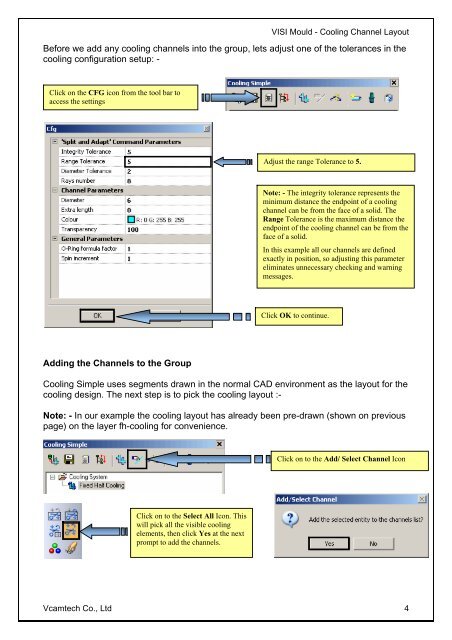
Before we add any cooling channels into the group, lets adjust one of the tolerances in the<br />
cooling configuration setup: -<br />
Click on the CFG icon from the tool bar to<br />
access the settings<br />
Adding the Channels to the Group<br />
<strong>Co</strong>oling Simple uses segments drawn in the normal CAD environment as the layout for the<br />
cooling design. The next step is to pick the cooling layout :-<br />
Note: - In our example the cooling layout has already been pre-drawn (shown on previous<br />
page) on the layer fh-cooling for convenience.<br />
Click on to the Select All Icon. This<br />
will pick all the visible cooling<br />
elements, then click Yes at the next<br />
prompt to add the channels.<br />
Adjust the range Tolerance to 5.<br />
Note: - The integrity tolerance represents the<br />
minimum distance the endpoint of a cooling<br />
channel can be from the face of a solid. The<br />
Range Tolerance is the maximum distance the<br />
endpoint of the cooling channel can be from the<br />
face of a solid.<br />
In this example all our channels are defined<br />
exactly in position, so adjusting this parameter<br />
eliminates unnecessary checking and warning<br />
messages.<br />
Click OK to continue.<br />
Click on to the Add/ Select Channel Icon<br />
Vcamtech <strong>Co</strong>., <strong>Ltd</strong> 4