- Page 1 and 2: VERO UK TRAINING MATERIAL Draft Ana
- Page 3: Start by opening the workfile: - VI
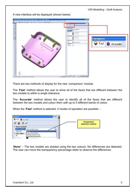
- Page 7 and 8: 9 1 2 VISI Modelling - Draft Analys
- Page 9 and 10: Modelling > Draft Faces Select refe
- Page 11 and 12: Analysis > Draft Analysis Select th
- Page 13 and 14: VISI Modelling - Draft Analysis NOT
- Page 15 and 16: VISI Modelling - Draft Analysis Usi
- Page 17 and 18: Analysis > Draft Analysis Select th
- Page 19 and 20: VISI Modelling - Draft Analysis 5.
- Page 21 and 22: From within the split line manager
- Page 23 and 24: VERO UK TRAINING MATERIAL Splitting
- Page 25 and 26: Start by opening the relevant workf
- Page 27 and 28: VISI Modelling - Splitting 8. SEARC
- Page 29 and 30: Select the direction - Select the Z
- Page 31 and 32: VISI Modelling - Splitting Note! If
- Page 33 and 34: VISI Modelling - Splitting At this
- Page 35 and 36: VERO UK TRAINING MATERIAL Game Cont
- Page 37 and 38: Start by opening the workfile: - Fi
- Page 39 and 40: VISI Modelling - Core Modification
- Page 41 and 42: Select the Create a new layer icon
- Page 43 and 44: 6 sheet bodies will be created VISI
- Page 45 and 46: Objectives VISI Mould - Tool Build
- Page 47 and 48: Setting the Tool Options VISI Mould
- Page 49 and 50: Delete the Insulation Plate from th
- Page 51 and 52: Adjust the Ejection side plate dime
- Page 53 and 54: Location Ring VISI Mould - Tool Bui
- Page 55 and 56:
Cap Head screws VISI Mould - Tool B
- Page 57 and 58:
Adjust Guide Pillar Lengths, Guidin
- Page 59 and 60:
VISI Mould - Tool Build Tutorial To
- Page 61 and 62:
Objectives VISI Mould - Tool Build
- Page 63 and 64:
VISI Mould - Tool Build Tutorial No
- Page 65 and 66:
Select the Z30 screw from the Fixin
- Page 67 and 68:
VISI Mould - Tool Build Tutorial Yo
- Page 69 and 70:
Now your turn - Quick Exercise - In
- Page 71 and 72:
VISI Mould - Tool Build Tutorial No
- Page 73 and 74:
The Result - Shows the Register Rin
- Page 75 and 76:
Inserting Ejector Pins (Hasco Z41 )
- Page 77 and 78:
VISI Mould - Tool Build Tutorial No
- Page 79 and 80:
Inserting Sub Gate Ejector 2 VISI M
- Page 81 and 82:
Objectives VISI Mould - Inserting L
- Page 83 and 84:
The display should look like the on
- Page 85 and 86:
Next select the stroke direction fo
- Page 87 and 88:
The Result VISI Mould - Inserting L
- Page 89 and 90:
VISI Mould - Inserting Lifters Now
- Page 91 and 92:
Objectives VISI Mould - Slide Assem
- Page 93 and 94:
Create the Slide body VISI Mould -
- Page 95 and 96:
The Result VISI Mould - Slide Assem
- Page 97 and 98:
VISI Mould - Slide Assembly Creatio
- Page 99 and 100:
VISI Mould - Slide Assembly Creatio
- Page 101 and 102:
VISI Mould - Slide Assembly Creatio
- Page 103 and 104:
VISI Mould - Slide Assembly Creatio
- Page 105 and 106:
Objectives VISI Mould - Cooling Cha
- Page 107 and 108:
VISI Mould - Cooling Channel Layout
- Page 109 and 110:
There should now be 14 channels in
- Page 111 and 112:
Check the diameter of the cooling c
- Page 113 and 114:
VISI Mould - Cooling Channel Layout
- Page 115 and 116:
VISI Mould - Cooling Channel Layout
- Page 117 and 118:
VISI Mould - Cooling Channel Layout
- Page 119 and 120:
Now activate all the layers on the
- Page 121 and 122:
Objectives VISI Mould - Creating Mo
- Page 123 and 124:
VISI Mould - Creating Mould Tool Do
- Page 125 and 126:
VISI Mould - Creating Mould Tool Do
- Page 127 and 128:
VISI Mould - Creating Mould Tool Do
- Page 129 and 130:
VISI Mould - Creating Mould Tool Do
- Page 131 and 132:
VISI Mould - Creating Mould Tool Do
- Page 133 and 134:
Numbering the Items using table mod
- Page 135 and 136:
VISI Mould - Creating Mould Tool Do
- Page 137 and 138:
VISI Mould - Creating Mould Tool Do
- Page 139 and 140:
VISI Mould - Creating Mould Tool Do
- Page 141 and 142:
VISI Mould - Creating Mould Tool Do