

Download Adept Cobra PLC600 User's Guide - pulsar.com.tr
Download Adept Cobra PLC600 User's Guide - pulsar.com.tr
Download Adept Cobra PLC600 User's Guide - pulsar.com.tr

You also want an ePaper? Increase the reach of your titles
YUMPU automatically turns print PDFs into web optimized ePapers that Google loves.
Optional Robot Equipment Installation<br />
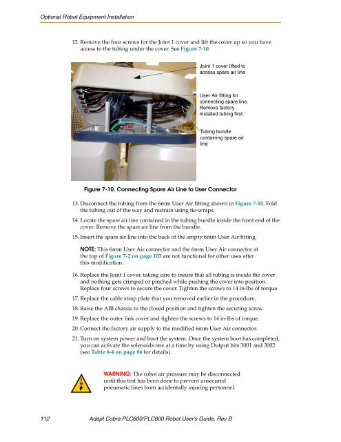
12. Remove the four screws for the Joint 1 cover and lift the cover up so you have<br />
access to the tubing under the cover. See Figure 7-10.<br />
Joint 1 cover lifted to<br />
access spare air line<br />
User Air fitting for<br />
connecting spare line.<br />
Remove factory<br />
installed tubing first.<br />
Tubing bundle<br />
containing spare air<br />
line<br />
Figure 7-10. Connecting Spare Air Line to User Connector<br />
13. Disconnect the tubing from the 6mm User Air fitting shown in Figure 7-10. Fold<br />
the tubing out of the way and res<strong>tr</strong>ain using tie-wraps.<br />
14. Locate the spare air line contained in the tubing bundle inside the front end of the<br />
cover. Remove the spare air line from the bundle.<br />
15. Insert the spare air line into the back of the empty 6mm User Air fitting.<br />
NOTE: This 6mm User Air connector and the 6mm User Air connector at<br />
the top of Figure 7-2 on page 103 are not functional for other uses after<br />
this modification.<br />
16. Replace the Joint 1 cover, taking care to insure that all tubing is inside the cover<br />
and nothing gets crimped or pinched while pushing the cover into position.<br />
Replace four screws to secure the cover. Tighten the screws to 14 in-lbs of torque.<br />
17. Replace the cable s<strong>tr</strong>ap plate that you removed earlier in the procedure.<br />
18. Raise the AIB chassis to the closed position and tighten the securing screw.<br />
19. Replace the outer link cover and tighten the screws to 14 in-lbs of torque.<br />
20. Connect the factory air supply to the modified 6mm User Air connector.<br />
21. Turn on system power and boot the system. Once the system boot has <s<strong>tr</strong>ong>com</s<strong>tr</strong>ong>pleted,<br />
you can activate the solenoids one at a time by using Output bits 3001 and 3002<br />
(see Table 6-4 on page 86 for details).<br />
WARNING: The robot air pressure may be disconnected<br />
until this test has been done to prevent unsecured<br />
pneumatic lines from accidentally injuring personnel.<br />
112 <s<strong>tr</strong>ong>Adept</s<strong>tr</strong>ong> <s<strong>tr</strong>ong>Cobra</s<strong>tr</strong>ong> <s<strong>tr</strong>ong>PLC600</s<strong>tr</strong>ong>/PLC800 Robot User’s <s<strong>tr</strong>ong>Guide</s<strong>tr</strong>ong>, Rev B


