

Online proceedings - EDA Publishing Association
Online proceedings - EDA Publishing Association
Online proceedings - EDA Publishing Association

Create successful ePaper yourself
Turn your PDF publications into a flip-book with our unique Google optimized e-Paper software.
7-9 October 2009, Leuven, Belgium<br />
parameterization of the shape is necessary. This is realized<br />
by defining the shape on a number of equidistant locations<br />
along the whole channel length. A piece-wise linear shape<br />
profile is then assumed between these points. Thus,<br />
intermediate values can be obtained by interpolation.<br />
This method has the advantages that it resolves the profile<br />
at a high spatial accuracy and that every variable has only<br />
local influence on the shape. This is in contrast with the<br />
parameterization that was used in [1], where the shape is<br />
represented by a smooth quadratic polynomial function. The<br />
coefficients of this polynomial were used as variables subject<br />
to optimization. Every variable has therefore an influence<br />
along the whole channel length. As we will show later on, the<br />
thermal resistance minimization shows a non-smooth optimal<br />
shape profile that cannot be captured by the parameterization<br />
by [1].<br />
The optimization problems (7) and (8) are solved<br />
numerically using a conjugate gradient method.<br />
IV.<br />
RESULTS AND DISCUSSION<br />
A. Minimal wall temperature gradient – minimization of J<br />
1<br />
Optimization of the microchannel heat sink is performed on<br />
an illustrative case, using a channel height of 600 µm,<br />
minimal fin width of 30 µm and chip length of 1 cm. The<br />
pressure drop is fixed at 0.6 bar and water was used as a<br />
coolant. Material properties are evaluated at 20 °C. This<br />
gives rise to the following model parameters: w = 0. 05 and<br />
f<br />
−6<br />
χ = 1.851⋅10<br />
. The simplified model without axial<br />
conduction (6) is used since in the optimum there is nearly no<br />
axial temperature gradient and thus negligible axial<br />
conduction. In addition this reduces the required<br />
computational effort.<br />
When optimizing with respect to a minimal temperature<br />
gradient, using objective function J 1<br />
, it is observed that a<br />
unique solution does not exist in particular circumstances.<br />
This occurs when the resulting shape has uniform wall<br />
temperature, which is the absolute optimum. We will refer to<br />
this later.<br />
A similar observation was encountered in [1]. To<br />
circumvent the non-uniqueness of the optimization problem,<br />
Bau made a linear combination with the thermal resistance<br />
objective function using a weighting factor. This<br />
methodology resulted in a well-posed optimization problem,<br />
but no justification on the choice of the weighting factor was<br />
made.<br />
In order to keep the distinction between the two objectives,<br />
we perform the optimization in another way. In our research,<br />
the inlet width and its corresponding aspect ratio α are set to<br />
0<br />
a fixed value. Since this value is directly related to the<br />
resulting wall temperature, the optimal solution becomes<br />
unique.<br />
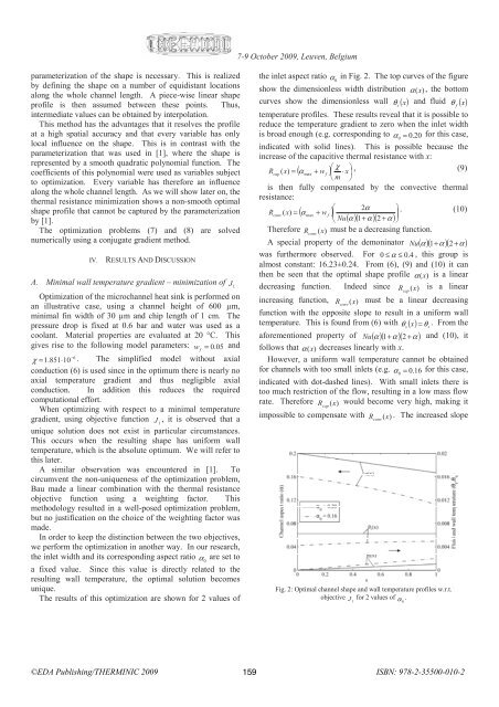
The results of this optimization are shown for 2 values of<br />
the inlet aspect ratio α in Fig. 2. The top curves of the figure<br />
0<br />
show the dimensionless width distribution α (x), the bottom<br />
curves show the dimensionless wall θ<br />
s<br />
( x)<br />
and fluid θ<br />
f<br />
( x)<br />
temperature profiles. These results reveal that it is possible to<br />
reduce the temperature gradient to zero when the inlet width<br />
is broad enough (e.g. corresponding to α = 0. 0<br />
20 for this case,<br />
indicated with solid lines). This is possible because the<br />
increase of the capacitive thermal resistance with x:<br />
⎛ χ ⎞<br />
Rcap<br />
( x)<br />
= ( α + w<br />
f<br />
) ⎜ ⋅ x⎟ , (9)<br />
max<br />
⎝ m ⎠<br />
is then fully compensated by the convective thermal<br />
resistance:<br />
⎛ 2α<br />
( )<br />
( )( )( ) ⎟ ⎞<br />
R ( x)<br />
= α<br />
max<br />
+ w ⎜<br />
. (10)<br />
conv<br />
f<br />
⎝ Nu α 1+<br />
α 2 + α ⎠<br />
Therefore R conv<br />
(x)<br />
must be a decreasing function.<br />
A special property of the demoninator Nu ( α )( 1+ α )( 2 + α )<br />
was furthermore observed. For 0 ≤ α ≤ 0. 4 , this group is<br />
almost constant: 16.23±0.24. From (6), (9) and (10) it can<br />
then be seen that the optimal shape profile α (x)<br />
is a linear<br />
decreasing function. Indeed since R cap<br />
(x)<br />
is a linear<br />
increasing function, R conv<br />
(x)<br />
must be a linear decreasing<br />
function with the opposite slope to result in a uniform wall<br />
temperature. This is found from (6) with θ<br />
s( x) = θ . From the<br />
s<br />
aforementioned property of Nu ( α )( 1+ α )( 2 + α ) and (10), it<br />
follows that α (x)<br />
decreases linearly with x.<br />
However, a uniform wall temperature cannot be obtained<br />
for channels with too small inlets (e.g. α = 0. 0<br />
16 for this case,<br />
indicated with dot-dashed lines). With small inlets there is<br />
too much restriction of the flow, resulting in a low mass flow<br />
rate. Therefore R cap<br />
(x)<br />
would become very high, making it<br />
impossible to compensate with R conv<br />
(x)<br />
. The increased slope<br />
Fig. 2: Optimal channel shape and wall temperature profiles w.r.t.<br />
objective J for 2 values of<br />
1<br />
α .<br />
0<br />
©<strong>EDA</strong> <strong>Publishing</strong>/THERMINIC 2009 159<br />
ISBN: 978-2-35500-010-2


