

Online proceedings - EDA Publishing Association
Online proceedings - EDA Publishing Association
Online proceedings - EDA Publishing Association

You also want an ePaper? Increase the reach of your titles
YUMPU automatically turns print PDFs into web optimized ePapers that Google loves.
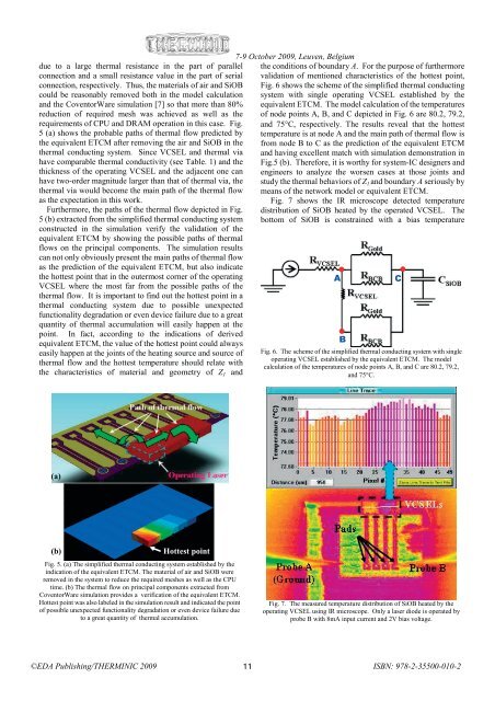
due to a large thermal resistance in the part of parallel<br />
connection and a small resistance value in the part of serial<br />
connection, respectively. Thus, the materials of air and SiOB<br />
could be reasonably removed both in the model calculation<br />
and the CoventorWare simulation [7] so that more than 80%<br />
reduction of required mesh was achieved as well as the<br />
requirements of CPU and DRAM operation in this case. Fig.<br />
5 (a) shows the probable paths of thermal flow predicted by<br />
the equivalent ETCM after removing the air and SiOB in the<br />
thermal conducting system. Since VCSEL and thermal via<br />
have comparable thermal conductivity (see Table. 1) and the<br />
thickness of the operating VCSEL and the adjacent one can<br />
have two-order magnitude larger than that of thermal via, the<br />
thermal via would become the main path of the thermal flow<br />
as the expectation in this work.<br />
Furthermore, the paths of the thermal flow depicted in Fig.<br />
5 (b) extracted from the simplified thermal conducting system<br />
constructed in the simulation verify the validation of the<br />
equivalent ETCM by showing the possible paths of thermal<br />
flows on the principal components. The simulation results<br />
can not only obviously present the main paths of thermal flow<br />
as the prediction of the equivalent ETCM, but also indicate<br />
the hottest point that in the outermost corner of the operating<br />
VCSEL where the most far from the possible paths of the<br />
thermal flow. It is important to find out the hottest point in a<br />
thermal conducting system due to possible unexpected<br />
functionality degradation or even device failure due to a great<br />
quantity of thermal accumulation will easily happen at the<br />
point. In fact, according to the indications of derived<br />
equivalent ETCM, the value of the hottest point could always<br />
easily happen at the joints of the heating source and source of<br />
thermal flow and the hottest temperature should relate with<br />
the characteristics of material and geometry of Z 1 and<br />
7-9 October 2009, Leuven, Belgium<br />
the conditions of boundary A. For the purpose of furthermore<br />
validation of mentioned characteristics of the hottest point,<br />
Fig. 6 shows the scheme of the simplified thermal conducting<br />
system with single operating VCSEL established by the<br />
equivalent ETCM. The model calculation of the temperatures<br />
of node points A, B, and C depicted in Fig. 6 are 80.2, 79.2,<br />
and 75°C, respectively. The results reveal that the hottest<br />
temperature is at node A and the main path of thermal flow is<br />
from node B to C as the prediction of the equivalent ETCM<br />
and having excellent match with simulation demonstration in<br />
Fig.5 (b). Therefore, it is worthy for system-IC designers and<br />
engineers to analyze the worsen cases at those joints and<br />
study the thermal behaviors of Z 1 and boundary A seriously by<br />
means of the network model or equivalent ETCM.<br />
Fig. 7 shows the IR microscope detected temperature<br />
distribution of SiOB heated by the operated VCSEL. The<br />
bottom of SiOB is constrained with a bias temperature<br />
A<br />
B<br />
Fig. 6. The scheme of the simplified thermal conducting system with single<br />
operating VCSEL established by the equivalent ETCM. The model<br />
calculation of the temperatures of node points A, B, and C are 80.2, 79.2,<br />
and 75°C.<br />
C<br />
(a)<br />
(b)<br />
Hottest point<br />
Fig. 5. (a) The simplified thermal conducting system established by the<br />
indication of the equivalent ETCM. The material of air and SiOB were<br />
removed in the system to reduce the required meshes as well as the CPU<br />
time. (b) The thermal flow on principal components extracted from<br />
CoventorWare simulation provides a verification of the equivalent ETCM.<br />
Hottest point was also labeled in the simulation result and indicated the point<br />
of possible unexpected functionality degradation or even device failure due<br />
to a great quantity of thermal accumulation.<br />
Fig. 7. The measured temperature distribution of SiOB heated by the<br />
operating VCSEL using IR microscope. Only a laser diode is operated by<br />
probe B with 8mA input current and 2V bias voltage.<br />
©<strong>EDA</strong> <strong>Publishing</strong>/THERMINIC 2009 11<br />
ISBN: 978-2-35500-010-2


