

Online proceedings - EDA Publishing Association
Online proceedings - EDA Publishing Association
Online proceedings - EDA Publishing Association

Create successful ePaper yourself
Turn your PDF publications into a flip-book with our unique Google optimized e-Paper software.
T junction<br />
Tinterface model 1<br />
are small, they can be reused and shared between the<br />
different design teams.<br />
Precisely, the methodology homogenizes the models at<br />
different integration levels to facilitate the share of the<br />
models. In that way, a designer builds finely its own model<br />
of interest using other available micro-models of materials<br />
and environments.<br />
Moreover, the Flex-CTM models contain few information<br />
of the original system. The geometrical and physical<br />
properties of the system are included implicitly in the model.<br />
Therefore, the models can preserve a confidentiality of the<br />
system properties.<br />
Finally, the Flex-CTM have the “Flexible” property.<br />
Meaning that each micro-model of the Flex-CTM can be<br />
modified independently and replaced by another one.<br />
VI. EVALUATION OF THE PERFORMANCES OF THE<br />
FLEX-CTM METHODOLOGY<br />
The methodology is evaluated with a simple co-simulation<br />
test case. The studied system is a die in a Ceramic Pin Grid<br />
Array (CPGA) package, plugged on a Printed Circuit Board<br />
(PCB). The typical use is an integrator who wants to<br />
characterize a board for a given component. The integrator<br />
may have obtained the die and package information in<br />
datasheets or even their micro-models. The geometry of the<br />
IC package is described Figure 6.<br />
Lid<br />
Step 2 Step 2<br />
Step 1 Die Step 1<br />
Substrate<br />
Pins<br />
PCB<br />
Figure 6: CPGA Geometrical Description<br />
To evaluate the influence of the board on which the<br />
component will be plugged, the component is connected to<br />
two different boards (Figure 7).<br />
a)<br />
b)<br />
Figure 7: Studied Printed Circuit Boards<br />
a) 1s0p<br />
b) 2s2p<br />
7-9 October 2009, Leuven, Belgium<br />
The model has been built with the typical values of the<br />
material thermal properties which can be found in the<br />
literature [11].<br />
The air layer surrounding the die is assumed to be<br />
insulating due to its very weak thermal conductivity. So, in<br />
this case a unique die-to-package heat flow path through the<br />
bottom face of the die is considered. The CPGA is<br />
simulated applying a uniform power source of 1W on the<br />
junction surface.<br />
A reference measure of the average temperature on the<br />
Die junction is obtained by simulating a FEM model of the<br />
full circuit. This measure is a reference to evaluate the<br />
methodology in terms of accuracy, model size and<br />
simulation time.<br />
The first step of the Flex-CTM methodology splits the<br />
CPGA geometry into 4 descriptions according to the<br />
physical properties (see Figure 8).<br />
Die<br />
Pins<br />
Figure 8: Model Splitting<br />
CPGA Package<br />
PCB<br />
The junction interface is on the top of the die and the<br />
model contains 3 coupling interfaces. The first one links the<br />
die to the package substrate, the second one links the<br />
package substrate to the pins and the last one links the pins<br />
to the PCB. The 4 (Die, Package, Pins, PCB) FEM models<br />
of the system are extracted in their respective numerical<br />
systems G 1,2,3,4 and C 1,2,3,4 with their related node properties.<br />
Concerning the heat transfer coefficients, they are identified<br />
using a commercial CFD tool. Then they are embedded in<br />
the CPGA Package and in the board models. The nodes<br />
belonging to the interfaces of the models are kept during the<br />
reduction process. TABLE I summarizes the number of<br />
nodes of each part at different steps of the methodology. The<br />
number in brackets indicates the number of external nodes<br />
kept of each micro-model.<br />
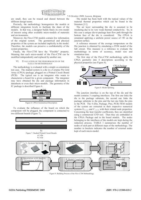
1. System Splitting 2. Model Extraction 3. Node Selection<br />
6. Simulation with Specific<br />
Condition Setting<br />
Mean tem peratures<br />
25<br />
5. Model Coupling 4. Model Reduction<br />
T [deg]<br />
20<br />
15<br />
T interface model 2<br />
10<br />
tim e [s]<br />
5<br />
0<br />
10 -6 10 -4 10 -2 10 0 10 2 10 4<br />
Lagrange Multipliers<br />
Figure 9: Building Process of the Flex-CTM Methodology<br />
G,C<br />
matrices<br />
©<strong>EDA</strong> <strong>Publishing</strong>/THERMINIC 2009 21<br />
ISBN: 978-2-35500-010-2


