Multilin 469 Motor Management Relay ... - GE Digital Energy
Multilin 469 Motor Management Relay ... - GE Digital Energy
Multilin 469 Motor Management Relay ... - GE Digital Energy

Create successful ePaper yourself
Turn your PDF publications into a flip-book with our unique Google optimized e-Paper software.
CHAPTER 3: INSTALLATION<br />
relays, being non-failsafe, will normally be de-energized and energize when called upon to<br />
operate. When the <strong>469</strong> control power is lost, these relays are de-energized and in their<br />
non-operated state. Shorting bars in the drawout case ensure that no trip or alarm occurs<br />
when the <strong>469</strong> is drawn out. However, the 6 SERVICE output will indicate that the <strong>469</strong> has<br />
been drawn out. Each output relay has an LED indicator on the front panel that turns on<br />
when the associated relay is in the operated state.<br />
<strong>Relay</strong> contacts must be considered unsafe to touch when the <strong>469</strong> is energized! If the<br />
output relay contacts are required for low voltage accessible applications, it is the<br />
customer's responsibility to ensure proper insulation levels.<br />
• 1TRIP: The trip relay should be wired to take the motor off line when conditions<br />
warrant. For a breaker application, the normally-open 1 TRIP contact should be wired<br />
in series with the Breaker trip coil. For contactor applications, the normally-closed<br />
1 TRIP contact should be wired in series with the contactor coil.<br />
Supervision of a breaker trip coil requires that the supervision circuit be in parallel with<br />
the 1 TRIP relay output contacts. With this connection made, the supervision input<br />
circuits place an impedance across the contacts that draws a 2 mA current (for an<br />
external supply voltage from 30 to 250 V DC) through the breaker trip coil. The<br />
supervision circuits respond to a loss of this trickle current as a failure condition.<br />
Circuit breakers equipped with standard control circuits have a breaker auxiliary<br />
contact permitting the trip coil to be energized only when the breaker is closed. When<br />
these contacts are open, as detected by the Starter Status <strong>Digital</strong> Input monitoring<br />
breaker auxiliary contacts, trip coil supervision circuit is automatically disabled. This<br />
logic allows the trip circuit to be monitored only when the breaker is closed.<br />
• 2 AUXILIARY, 3 AUXILIARY: The auxiliary relays may be programmed for trip echo,<br />
alarm echo, trip backup, alarm differentiation, control circuitry, and numerous other<br />
functions. They should be wired as configuration warrants.<br />
• 4ALARM: The alarm relay should connect to the appropriate annunciator or<br />
monitoring device.<br />
• 5BLOCKSTART: This relay should be wired in series with the start pushbutton in either<br />
a breaker or contactor configuration to prevent motor starting. When a trip has not<br />
been reset on a breaker, the block start relay prevents a start attempt that would<br />
result in an immediate trip. Any lockout functions are also directed to the block start<br />
relay.<br />
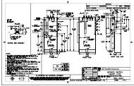
• 6SERVICE: The service relay operates if any of the <strong>469</strong> diagnostics detect an internal<br />
failure or on loss of control power. This output may be monitored with an annunciator,<br />
PLC or DCS. If it is deemed that a motor is more important than a process, the service<br />
relay normally-closed contact may also be wired in parallel with the trip relay on a<br />
breaker application or the normally-open contact may be wired in series with the trip<br />
relay on a contactor application. This will provide failsafe operation of the motor; that<br />
is, the motor will be tripped off line in the event that the <strong>469</strong> is not protecting it. If<br />
however, the process is critical, annunciation of such a failure will allow the operator<br />
or the operation computer to either continue, or do a sequenced shutdown. See the<br />
following figure for details.<br />
<strong>469</strong> MOTOR MANA<strong>GE</strong>MENT RELAY – INSTRUCTION MANUAL 3–23