- Page 2 and 3:
STEVENS PARK GOLF COURCE MAINTENANC
- Page 4 and 5:
26 24 16 Lighting and Branch Panelb
- Page 6 and 7:
B. Manufacturer Qualifications: A f
- Page 8 and 9:
1. For concrete surfaces exposed to
- Page 10 and 11:
k. Rich Seal 18 percent E; Richmond
- Page 12 and 13:
2.13 FABRICATING REINFORCEMENT A. F
- Page 14 and 15:
placing concrete, taking precaution
- Page 16 and 17:
F. Cold-Weather Placement: Comply w
- Page 18 and 19:
D. Unformed Surfaces: Begin curing
- Page 20 and 21:
2. Slump: ASTM C 143; one test at p
- Page 22 and 23:
C. Determination of Average Strengt
- Page 24 and 25:
Attachment B Documentation of Avera
- Page 26 and 27:
B. LEED Submittal: 1. Product Data
- Page 28 and 29:
2.03 NON-LOAD-BEARING WALL FRAMING
- Page 30 and 31:
3. Fasten cold-formed metal framing
- Page 32 and 33:
3. Bridging: Combination of flat, t
- Page 34 and 35:
C. Mill Certificates: Signed by man
- Page 36 and 37:
the load imposed when installed in
- Page 38 and 39:
A. Fabricate metal bollards from Sc
- Page 40 and 41:
06 10 00 ROUGH CARPENTRY 1.00 GENER
- Page 42 and 43:
C. For concealed boards, provide lu
- Page 44 and 45:
06 40 23 INTERIOR ARCHITECTURAL WOO
- Page 46 and 47:
2.02 MATERIALS A. General: Provide
- Page 48 and 49:
1. Trial fit assemblies at fabricat
- Page 50 and 51:
2. Secure backsplashes to tops with
- Page 52 and 53:
. Marlite. c. Nudo Products, Inc. 2
- Page 54 and 55:
07 92 00 JOINT SEALANTS 1.00 GENERA
- Page 56 and 57:
a. For joints with dissimilar subst
- Page 58 and 59:
o. Pecora Corporation; 865. p. Peco
- Page 60 and 61:
2.04 JOINT-SEALANT BACKING A. Gener
- Page 62 and 63:
5. Provide recessed joint configura
- Page 64 and 65:
08 11 13 HOLLOW METAL DOORS AND FRA
- Page 66 and 67:
2.02 MATERIALS 5. Security Metal Pr
- Page 68 and 69:
D. Hollow Metal Frames: Where frame
- Page 70 and 71:
f. Check plumbness, squareness, and
- Page 72 and 73:
C. Forest Certification: Provide do
- Page 74 and 75:
2.04 FABRICATION A. Factory machine
- Page 76 and 77:
08 33 23 OVERHEAD COILING DOORS 1.0
- Page 78 and 79:
ASTM A 123/A 123M. Slot bolt holes
- Page 80 and 81:
08 71 00 DOOR HARDWARE 1.00 GENERAL
- Page 82 and 83:
C. Deliver keys to manufacturer of
- Page 84 and 85:
2.04 LOCKS AND LATCHES, GENERAL A.
- Page 86 and 87:
2.09 KEYING 3. ASSA, Inc.; an ASSA
- Page 88 and 89:
14. Rixson Specialty Door Controls;
- Page 90 and 91:
B. Examine roughing-in for electric
- Page 92 and 93:
1 each Drip Cap NGP 16A Door Hardwa
- Page 94 and 95:
D. Bituminous Paint: Cold-applied a
- Page 96 and 97:
09 22 16 NON-STRUCTURAL METAL FRAMI
- Page 98 and 99:
C. Firestop Tracks: Top runner manu
- Page 100 and 101:
F. Installation Tolerances: Install
- Page 102 and 103:
1.06 PROJECT CONDITIONS A. Environm
- Page 104 and 105:
B. Steel Drill Screws: ASTM C 1002,
- Page 106 and 107:
C. Interior Trim: Install in the fo
- Page 108 and 109:
09 51 13 ACOUSTICAL PANEL CEILINGS
- Page 110 and 111:
D. Wire Hangers, Braces, and Ties:
- Page 112 and 113:
09 65 13 RESILIENT BASE AND ACCESSO
- Page 114 and 115:
G. Inside Corners: Job formed. H. F
- Page 116 and 117:
2. Sweep and vacuum surfaces thorou
- Page 118 and 119:
1. Critical Radiant Flux Classifica
- Page 120 and 121:
4. Moisture Testing: Perform tests
- Page 122 and 123:
09 91 13 EXTERIOR PAINTING 1.00 GEN
- Page 124 and 125:
2.04 METAL PRIMERS A. Alkyd Anticor
- Page 126 and 127:
3.03 APPLICATION A. Apply paints ac
- Page 128 and 129:
09 91 23 INTERIOR PAINTING 1.00 0BG
- Page 130 and 131:
B. 35BChemical Components of Field-
- Page 132 and 133:
3.02 18BPREPARATION A. 5BComply wit
- Page 134 and 135:
3.05 21BINTERIOR PAINTING SCHEDULE
- Page 136 and 137:
2. Manufacturer's Information: Manu
- Page 138 and 139:
D. Material Compatibility: Provide
- Page 140 and 141:
sticky under moderate thumb pressur
- Page 142 and 143:
10 28 00 TOILET, BATH AND LAUNDRY A
- Page 144 and 145:
1. Plumberex Specialty Products, In
- Page 146 and 147:
B. Aluminum: Alloy and temper recom
- Page 148 and 149:
2.05 ALUMINUM FINISHES A. Color Ano
- Page 150 and 151:
10 44 16 FIRE EXTINGUISHERS 1.00 GE
- Page 152 and 153:
3.02 INSTALLATION A. General: Insta
- Page 154 and 155:
1.04 SYSTEM DESCRIPTION A. General:
- Page 156 and 157:
8. Accessories. B. Shop Drawings: F
- Page 158 and 159:
1.07 QUALITY ASSURANCE A. Erector Q
- Page 160 and 161:
1.11 WARRANTY A. Special Warranty o
- Page 162 and 163:
N. Primer: SSPC-Paint 15, Type I, r
- Page 164 and 165:
. Join flanges to webs of built-up
- Page 166 and 167:
2. Panel Coverage: 36 inches (914 m
- Page 168 and 169:
2. Clips: Manufacturer's standard,
- Page 170 and 171:
d. Radiographic Inspection: ASTM E
- Page 172 and 173:
3.04 METAL PANEL INSTALLATION, GENE
- Page 174 and 175:
3.07 TRANSLUCENT PANEL INSTALLATION
- Page 176 and 177:
2. Expansion Provisions: Provide fo
- Page 178 and 179:
3.15 DEMONSTRATION A. Engage a fact
- Page 180 and 181: 3. Fire alarm signal shall initiate
- Page 182 and 183: E. Electrical Components, Devices,
- Page 184 and 185: 2.03 MANUAL FIRE ALARM BOXES A. Des
- Page 186 and 187: 72 4-4 “Visible Characteristics,
- Page 188 and 189: 21 11 00 FACILITY FIRE SUPRESSION W
- Page 190 and 191: 1.05 JOB CONDITIONS A. The fire pro
- Page 192 and 193: D. Install piping to allow for expa
- Page 194 and 195: 21 13 13 DRY-PIPE SPRINKLER SYSTEMS
- Page 196 and 197: 2.00 PRODUCTS 2.01 MATERIALS A. SPR
- Page 198 and 199: 22 00 01 PLUMBING SYSTEMS 1.00 GENE
- Page 200 and 201: 2.00 PRODUCTS 2.01 PIPE AND FITTING
- Page 202 and 203: 3. CPVC and PVC Butterfly valves: 1
- Page 204 and 205: through the wall frame including st
- Page 206 and 207: presloped with a minimum .06% slope
- Page 208 and 209: ACCEPTABLE MANUFACTURERS ProVent Sy
- Page 210 and 211: V. SAND AND SOILDS INTERCEPTORS 1.
- Page 212 and 213: 3.00 EXECUTION pattern is not obvio
- Page 214 and 215: the public from open trenches. Erec
- Page 216 and 217: 23 00 00 BASIC MECHANICAL MATERIALS
- Page 218 and 219: D. Plastic, Pipe-Flange Gasket, Bol
- Page 220 and 221: E. Place grout, completely filling
- Page 222 and 223: d. Other design parameters such as
- Page 224 and 225: 23 05 93 TESTING, ADJUSTING, AND BA
- Page 226 and 227: G. Examine HVAC system and equipmen
- Page 228 and 229: a. Measure outlet static pressure a
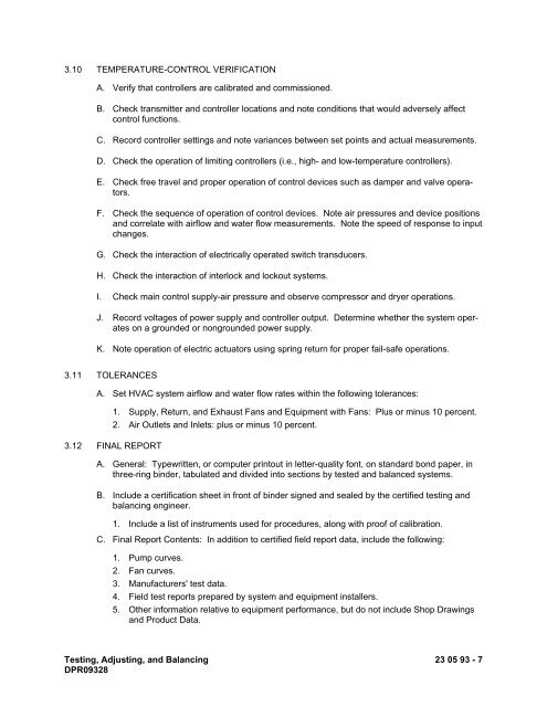
- Page 232 and 233: B. Seasonal Periods: If initial TAB
- Page 234 and 235: 1.07 SCHEDULING A. Schedule insulat
- Page 236 and 237: K. Insulation Terminations: For ins
- Page 238 and 239: 1. Material: Mineral-fiber blanket.
- Page 240 and 241: 2.00 PRODUCTS 2.01 MANUFACTURERS A.
- Page 242 and 243: M. Insulation Terminations: For ins
- Page 244 and 245: 3.09 INTERIOR INSULATION APPLICATIO
- Page 246 and 247: B. Galvanized Sheet Steel: Lock-for
- Page 248 and 249: D. Install couplings tight to duct
- Page 250 and 251: E. Mechanical Cleaning Methodology:
- Page 252 and 253: 2. Roll-Formed Steel Blades: 0.064-
- Page 254 and 255: 23 34 23 POWER VENTILATORS 1.00 GEN
- Page 256 and 257: 3. Propeller Fans: a. Aerovent; a T
- Page 258 and 259: 2.05 MOTORS A. Refer to Division 23
- Page 260 and 261: 23 37 13 DIFFUSERS, REGISTERS, AND
- Page 262 and 263: 23 81 26 SPLIT-SYSTEM AIR-CONDITION
- Page 264 and 265: will occur as a result of overflow
- Page 266 and 267: B. Verify that units are installed
- Page 268 and 269: 2.05 FAN terminal box. Fin surface
- Page 270 and 271: 26 05 00 COMMON WORK RESULTS FOR EL
- Page 272 and 273: 1.05 DELIVERY AND STORAGE A. Follow
- Page 274 and 275: D. All construction areas shall be
- Page 276 and 277: B. SINGLE CONDUCTORS: Conductor wit
- Page 278 and 279: 26 05 19.01 WIRE CONNECTIONS AND DE
- Page 280 and 281:
26 05 26 GROUNDING & BONDING FOR EL
- Page 282 and 283:
G. Metal conduits stubbed up into s
- Page 284 and 285:
26 05 29 HANGERS AND SUPPORTS FOR E
- Page 286 and 287:
B. Maximum Support Spacing and Mini
- Page 288 and 289:
26 05 33.01 CONDUITS 1.00 GENERAL 1
- Page 290 and 291:
O. THREADED NIPPLES: As manufacture
- Page 292 and 293:
2. Grade underground and outdoor co
- Page 294 and 295:
26 05 33.02 WIREWAYS 1.00 GENERAL 1
- Page 296 and 297:
C. Unless otherwise noted, location
- Page 298 and 299:
C. PULL AND JUNCTION BOXES: Metal c
- Page 300 and 301:
2. Provide conductor tags for condu
- Page 302 and 303:
1. Color-Coding for Phase Identific
- Page 304 and 305:
NO TEXT FOR THIS PAGE Identificatio
- Page 306 and 307:
5. A relay coordination study shall
- Page 308 and 309:
2.00 EXECUTION 2.01 GENERAL A. Prov
- Page 310 and 311:
B. The CONTRACTOR shall adjust all
- Page 312 and 313:
26 09 23 LIGHTING CONTROL DEVICES 1
- Page 314 and 315:
F. A dedicated photocell input shal
- Page 316 and 317:
26 24 16 LIGHTING AND BRANCH PANELB
- Page 318 and 319:
D. Each circuit breaker used in 208
- Page 320 and 321:
26 27 26 WIRING DEVICES 1.00 GENERA
- Page 322 and 323:
A. Comply with NECA 1, including th
- Page 324 and 325:
26 28 16 ENCLOSED SWITCHES AND CIRC
- Page 326 and 327:
26 29 13 ENCLOSED CONTROLLERS 1.00
- Page 328 and 329:
D. CONTROL POWER: Control power sha
- Page 330 and 331:
H. Wiring in the combination starte
- Page 332 and 333:
B. IEC or dual rated NEMA/IEC equip
- Page 334 and 335:
5. Test each motor for proper phase
- Page 336 and 337:
2.00 PRODUCTS 2.01 MATERIALS A. Mat
- Page 338 and 339:
3.02 FIELD QUALITY CONTROL A. The l
- Page 340 and 341:
D. LAMPS 1. FLUORESCENT: Cool white
- Page 342 and 343:
31 23 10 STRUCTURAL EXCAVATION AND
- Page 344 and 345:
3.00 EXECUTION 3.01 PREPARATION Cle
- Page 346:
3. Areas of the fill being compacte


