The <str<strong>on</strong>g>12th</str<strong>on</strong>g> <str<strong>on</strong>g>Internati<strong>on</strong>al</str<strong>on</strong>g> <str<strong>on</strong>g>Symposium</str<strong>on</strong>g> <strong>on</strong> <strong>District</strong> <strong>Heating</strong> <strong>and</strong> <strong>Cooling</strong>,September 5 th to September 7 th , 2010, Tallinn, Est<strong>on</strong>iaThis system is called a rigid system with a tightc<strong>on</strong>necti<strong>on</strong> between the service pipe, the foam <strong>and</strong>outer casing. Once it is formed, this product cannot bere-used in own process.Fig. 4. Secti<strong>on</strong> view of Steel/PUR pipeextruder. Once the material flows out of the extruder,the pressure drop causes the expansi<strong>on</strong> of thehydrocarb<strong>on</strong>. The aggregati<strong>on</strong> state of the moleculechanges from liquid into gas.Examples of hydrocarb<strong>on</strong> gases that can be used are:LPG, Butane or Isobutane. And just like the PUR foamthere is a degassing effect: the exchange of theblowing agent with air will increase the heat loss of theproduct. This effect is shown in ‗Heat loss of flexibleplastic pipe systems, analysis <strong>and</strong> optimizati<strong>on</strong>‘ byE.J.H.M. van der Ven et al. [4].Foam producti<strong>on</strong> processesThe insulati<strong>on</strong> foams described in this paper are madeof Poly-urethane (PUR) foam, Poly-ethylene (PE) foamor cross linked Poly-ethylene foam (PE-Xa). Thesefoams have different properties. Some of theseproperties influence the heat loss properties of thecomplete product.Polyurethane (PUR) foamPUR foam is a thermo-set foam. It is made out of twochemicals, a Poly-alcohol <strong>and</strong> an Iso-cyanate. Thesematerials react <strong>and</strong> the Polyurethane is formed. Thisreacti<strong>on</strong> is irreversible, so the material can never returninto its original chemicals. The blowing agent for thiskind of foam can be Carb<strong>on</strong> Dioxide, Nitrogen orHydrocarb<strong>on</strong> molecules, for instance Cyclopentane orButane.If Hydrocarb<strong>on</strong> gases are used, these gases str<strong>on</strong>glyinfluence the heat loss performance of the preinsulatedsystem. These gases have different thermalc<strong>on</strong>ductivities compared with air. After producti<strong>on</strong> of thefoam an exchange with air starts. A product that isfreshly made c<strong>on</strong>tains a high percentage ofHydrocarb<strong>on</strong> gases. At this point in time the productwill have the lowest heat loss possible. If the sameproduct is for instance three years old it c<strong>on</strong>tains moreair <strong>and</strong> less Hydrocarb<strong>on</strong> gases due to gas diffusi<strong>on</strong>.And so the product will have a higher heat losscompared to the fresh product. The process ofdegassing is described in research papers ‗L<strong>on</strong>g termheat loss of plastic Polybutylene piping systems‘ by S.de Boer et al. [3].Poly-ethylene (PE) foamPE foam is a thermoplastic foam. Once it is formed, itcan go back to its original state by heating it above itsmelting point. Because of this property, it is possible tore-use these kinds of foams.The foaming process to make PE foam is called the―physical foaming process‖. A Hydrocarb<strong>on</strong> molecule ismixed into the PE matrix under high pressure in an121Cross linked Poly-ethylene foam (PE-Xa)Although cross linked PE foam (x-PE) is also made ofPE, there is a big difference compared to PE foam: thetype of Blowing agent.The foaming process to make x-PE foam is called the―chemical foaming process‖. In this case a chemical ismixed into the PE matrix. The blowing agent can forinstance be Azodicarb<strong>on</strong>amide. While heating thematrix, the chemical starts decomposing <strong>and</strong> gases arereleased. These gases are Carb<strong>on</strong> dioxide <strong>and</strong>Nitrogen. The thermal c<strong>on</strong>ductivity of these gases ismore or less equal to the thermal c<strong>on</strong>ductivity of air. Sothe aging effect of this product in relati<strong>on</strong> to the heatloss is less.To make this foaming process possible, it is necessaryto c<strong>on</strong>nect the Poly-ethylene chains with each other.This is called the cross link. The complete process tomake x-PE foam is called the ―chemical foamingprocess with cross link‖. To make the comparis<strong>on</strong> withPE foam complete: this process is called the ―physicalfoaming process without cross link‖.The blowing agent is not the <strong>on</strong>ly additive thatinfluences the thermal c<strong>on</strong>ductivity of the foam <strong>and</strong>therefore the heat loss properties of the pre-insulatedsystem. Also other additives can influence the thermalc<strong>on</strong>ductivity of PE foam.Nucleating agents will influence the cell structure of thefoam. As a basic rule: the finer the foam the lower thethermal c<strong>on</strong>ductivity. With this additive the c<strong>on</strong>vecti<strong>on</strong>part of the insulati<strong>on</strong> material will be influenced.Another additive that influences the thermalc<strong>on</strong>ductivity is an anti-radiati<strong>on</strong> additive. By using thisspecial kind of additive it is possible to create areflecti<strong>on</strong> of radiati<strong>on</strong> energy.HEAT LOSS TEST METHODThis chapter briefly describes the test rig <strong>and</strong> testmethod used to determine the absolute heat losses ofthe different types of pre-insulated pipes.
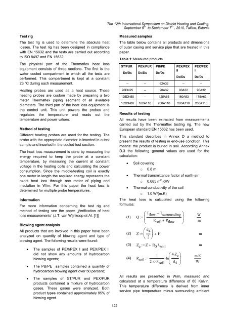
The <str<strong>on</strong>g>12th</str<strong>on</strong>g> <str<strong>on</strong>g>Internati<strong>on</strong>al</str<strong>on</strong>g> <str<strong>on</strong>g>Symposium</str<strong>on</strong>g> <strong>on</strong> <strong>District</strong> <strong>Heating</strong> <strong>and</strong> <strong>Cooling</strong>,September 5 th to September 7 th , 2010, Tallinn, Est<strong>on</strong>iaTest rigThe test rig is used to determine the absolute heatlosses. The test rig has been designed in compliancewith EN 15632 <strong>and</strong> the tests are carried out accordingto ISO 8497 <strong>and</strong> EN 15632.The physical part of the Thermaflex heat lossequipment c<strong>on</strong>sists of three secti<strong>on</strong>s. The first is thewater cooled compartment in which all the tests areperformed. This compartment is kept at a c<strong>on</strong>stant23 °C during each measurement.<strong>Heating</strong> probes are used as a heat source. Theseheating probes are custom made by preparing a twometer Thermaflex piping segment of all availablediameters. The third part of the heat loss equipment isthe c<strong>on</strong>trol unit. This unit powers the probes <strong>and</strong>regulates the temperature <strong>and</strong> reads out thetemperature <strong>and</strong> power values.Method of testingDifferent heating probes are used for the testing. Theprobe with the appropriate diameter is inserted in a testsample <strong>and</strong> inserted in the cooled test secti<strong>on</strong>.The heat loss measurement is d<strong>on</strong>e by measuring theenergy required to keep the probe at a c<strong>on</strong>stanttemperature, by measuring the current at c<strong>on</strong>stantvoltage in the heating coils <strong>and</strong> calculating the powerc<strong>on</strong>sumpti<strong>on</strong>. Since the middle/testing coil is exactly<strong>on</strong>e meter in length the required energy represents theexact heat loss through <strong>on</strong>e meter of piping <strong>and</strong>insulati<strong>on</strong> in W/m. For this paper the heat loss isdetermined for multiple probe temperatures.Informati<strong>on</strong>For more informati<strong>on</strong> c<strong>on</strong>cerning the test rig <strong>and</strong>method of testing see the paper ‗Verificati<strong>on</strong> of heatloss measurements‘ (J.T. van Wijnkoop et Al. [1])Blowing agent analysisAll products that are involved in this paper have beenanalyzed <strong>on</strong> quantity of blowing agent <strong>and</strong> type ofblowing agent. The following results were found:The samples of PEX/PEX I <strong>and</strong> PEX/PEX IIdid not show any amounts of hydrocarb<strong>on</strong>blowing agents;The PB/PE samples c<strong>on</strong>tained a quantity ofhydrocarb<strong>on</strong> blowing agent over 50 percent;The samples of ST/PUR <strong>and</strong> PEX/PURproducts c<strong>on</strong>tained a mixture of hydrocarb<strong>on</strong>gases. These gases were analyzed. Bothproduct types c<strong>on</strong>tained approximately 95% ofblowing agent.Measured samplesThe table below c<strong>on</strong>tains all products <strong>and</strong> dimensi<strong>on</strong>sof outer casing <strong>and</strong> service pipe that are treated in thispaper.Table 1: Measured productsST/PURDc/DsPEX/PURDc/DsPB/PEDc/DsPEX/PEXIIDc/DsPEX/PEXIDc/Ds-- -- 62A32 -- --90DN25 -- 90A32 90A32 90A32125DN50 -- 125A63 160A63 175A63162DN80 162A110 200A110 200A110 200A110Results of testingAll results have been extracted from measurementscarried out by the Thermaflex testing rig. The newEuropean st<strong>and</strong>ard EN 15632 has been used.This st<strong>and</strong>ard describes in Annex D a method topresent the results of testing in end-use c<strong>on</strong>diti<strong>on</strong>. Thismeans: the product is buried in soil. According AnnexD.3 the following general values are used for thecalculati<strong>on</strong>:Soil coveringo0.8 mThermal transmittance factor of earth-airo0.685 m 2 .K/WThermal c<strong>on</strong>ductivity of the soilo1.0 W/(m.K)The heat loss is calculated using the followingformulas:(1) Q (2) Z T flow T surroundingd 42R soil R flow H(3) Z c Z R 0 soil1(4) R soil ln2 soil4Z cd 4WmmmmKAll results are presented in W/m, measured <strong>and</strong>calculated at a temperature difference of 60 Kelvin.This temperature difference is derived from innerservice pipe temperature minus surrounding ambientW122
- Page 1:
12th Inter
- Page 5 and 6:
The 12th I
- Page 7 and 8:
The 12th I
- Page 10 and 11:
The 12th I
- Page 12 and 13:
The 12th I
- Page 14 and 15:
For the case of parallel buried pip
- Page 16 and 17:
The 12th I
- Page 18 and 19:
The 12th I
- Page 20 and 21:
The 12th I
- Page 22 and 23:
The 12th I
- Page 24 and 25:
The 12th I
- Page 26 and 27:
The 12th I
- Page 28 and 29:
The 12th I
- Page 30 and 31:
The 12th I
- Page 32 and 33:
The 12th I
- Page 34 and 35:
The 12th I
- Page 36 and 37:
The 12th I
- Page 38 and 39:
The 12th I
- Page 40 and 41:
The 12th I
- Page 42 and 43:
The 12th I
- Page 44 and 45:
The 12th I
- Page 46 and 47:
The 12th I
- Page 48 and 49:
The 12th I
- Page 50 and 51:
The 12th I
- Page 52 and 53:
The 12th I
- Page 54 and 55:
The 12th I
- Page 56 and 57:
The 12th I
- Page 58 and 59:
The 12th I
- Page 60 and 61:
The 12th I
- Page 62 and 63:
The 12th I
- Page 64 and 65:
The 12th I
- Page 66 and 67:
The 12th I
- Page 68 and 69:
The 12th I
- Page 70 and 71:
The 12th I
- Page 72 and 73: The 12th I
- Page 74 and 75: The 12th I
- Page 76 and 77: The 12th I
- Page 78 and 79: The 12th I
- Page 80 and 81: The 12th I
- Page 82 and 83: The 12th I
- Page 84 and 85: The 12th I
- Page 86 and 87: The 12th I
- Page 88 and 89: The 12th I
- Page 90 and 91: The 12th I
- Page 92 and 93: The 12th I
- Page 94 and 95: The 12th I
- Page 96 and 97: The 12th I
- Page 98 and 99: the street the more shallow the sha
- Page 100 and 101: The 12th I
- Page 102 and 103: The 12th I
- Page 104 and 105: The 12th I
- Page 106 and 107: The 12th I
- Page 108 and 109: The 12th I
- Page 110 and 111: P-1P-4P-9P-7E-5P-14P-8The 1
- Page 112 and 113: The 12th I
- Page 114 and 115: The 12th I
- Page 116 and 117: The 12th I
- Page 118 and 119: The 12th I
- Page 120 and 121: The 12th I
- Page 124 and 125: The 12th I
- Page 126 and 127: The 12th I
- Page 128 and 129: The 12th I
- Page 130 and 131: The 12th I
- Page 132 and 133: The 12th I
- Page 134 and 135: The 12th I
- Page 136 and 137: The 12th I
- Page 138 and 139: to heating costs of 14,5 ct/kWh. Th
- Page 140 and 141: The 12th I
- Page 142 and 143: The 12th I
- Page 144 and 145: The 12th I
- Page 146 and 147: The 12th I
- Page 148 and 149: academic access is facilitated as t
- Page 150 and 151: The 12th I
- Page 152 and 153: The 12th I
- Page 154 and 155: The 12th I
- Page 156 and 157: The 12th I
- Page 158 and 159: The 12th I
- Page 160 and 161: The 12th I
- Page 162 and 163: 1. CHP system operation in A2. Ther
- Page 164 and 165: The 12th I
- Page 166 and 167: is covered by operating HOB. In oth
- Page 168 and 169: The 12th I
- Page 170 and 171: The 12th I
- Page 172 and 173:
The 12th I
- Page 174 and 175:
The 12th I
- Page 176 and 177:
The 12th I
- Page 178 and 179:
The 12th I
- Page 180 and 181:
The 12th I
- Page 182 and 183:
The 12th I
- Page 184 and 185:
The 12th I
- Page 186 and 187:
The 12th I
- Page 188 and 189:
The 12th I
- Page 190 and 191:
The 12th I
- Page 192 and 193:
The 12th I
- Page 194 and 195:
The 12th I
- Page 196 and 197:
produce heat and electricity. Fluct
- Page 198 and 199:
The 12th I
- Page 200 and 201:
The 12th I
- Page 202 and 203:
The 12th I
- Page 204 and 205:
The 12th I
- Page 206 and 207:
The 12th I
- Page 208 and 209:
The 12th I
- Page 210 and 211:
To assure that the temperatures mea
- Page 212 and 213:
The 12th I
- Page 214 and 215:
The 12th I
- Page 216 and 217:
The 12th I
- Page 218 and 219:
The 12th I
- Page 220 and 221:
production and provide for marginal
- Page 222 and 223:
The 12th I
- Page 224 and 225:
The 12th I
- Page 226 and 227:
The 12th I
- Page 228 and 229:
The 12th I
- Page 230 and 231:
The 12th I
- Page 232 and 233:
The 12th I
- Page 234 and 235:
The 12th I
- Page 236 and 237:
The 12th I
- Page 238 and 239:
The 12th I
- Page 240 and 241:
The 12th I
- Page 242 and 243:
In addition, it can also be observe
- Page 244 and 245:
The 12th I
- Page 246 and 247:
owner is normally only interested i
- Page 248 and 249:
The 12th I
- Page 250 and 251:
The 12th I
- Page 252 and 253:
The 12th I
- Page 254 and 255:
The 12th I
- Page 256 and 257:
The 12th I
- Page 258 and 259:
The 12th I
- Page 260 and 261:
The 12th I
- Page 262 and 263:
The 12th I
- Page 264 and 265:
The 12th I
- Page 266 and 267:
The 12th I
- Page 268 and 269:
The 12th I
- Page 270 and 271:
The 12th I
- Page 272 and 273:
The 12th I
- Page 274 and 275:
The 12th I
- Page 276 and 277:
The 12th I
- Page 278 and 279:
The 12th I
- Page 280 and 281:
The 12th I
- Page 282 and 283:
The 12th I
- Page 284 and 285:
The 12th I
- Page 286 and 287:
The 12th I
- Page 288 and 289:
The 12th I
- Page 290 and 291:
Stockholm district heating system a
- Page 292 and 293:
The 12th I
- Page 294 and 295:
The 12th I
- Page 296 and 297:
The 12th I
- Page 298 and 299:
The 12th I
- Page 300 and 301:
The 12th I
- Page 302 and 303:
The 12th I
- Page 304 and 305:
The 12th I
- Page 306 and 307:
The 12th I
- Page 308 and 309:
The 12th I
- Page 310 and 311:
The 12th I
- Page 312 and 313:
The 12th I
- Page 314 and 315:
The values presented do of course l
- Page 316 and 317:
The 12th I
- Page 318 and 319:
The 12th I
- Page 320 and 321:
The 12th I
- Page 322 and 323:
The 12th I
- Page 324 and 325:
The 12th I
- Page 326:
The 12th I