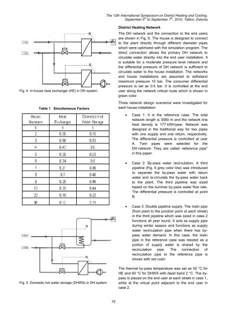
The <str<strong>on</strong>g>12th</str<strong>on</strong>g> <str<strong>on</strong>g>Internati<strong>on</strong>al</str<strong>on</strong>g> <str<strong>on</strong>g>Symposium</str<strong>on</strong>g> <strong>on</strong> <strong>District</strong> <strong>Heating</strong> <strong>and</strong> <strong>Cooling</strong>,September 5 th to September 7 th , 2010, Tallinn, Est<strong>on</strong>iaFig. 4 In-house heat exchanger (HE) in DH systemTable 1 Simultaneous Factors<strong>District</strong> <strong>Heating</strong> NetworkThe DH network <strong>and</strong> the c<strong>on</strong>necti<strong>on</strong> to the end usersare shown in Fig. 6. The house is designed to c<strong>on</strong>nectto the plant directly through different diameter pipeswhich were optimized with the simulati<strong>on</strong> program. Thedirect c<strong>on</strong>necti<strong>on</strong> allows the primary DH network tocirculate water directly into the end user installati<strong>on</strong>. Itis suitable for a moderate pressure level network <strong>and</strong>the differential pressure of DH network is sufficient tocirculate water to the house installati<strong>on</strong>. The networks<strong>and</strong> house installati<strong>on</strong>s are assumed to withst<strong>and</strong>maximum pressure 10 bar. The c<strong>on</strong>sumer differentialpressure is set as 0.5 bar. It is c<strong>on</strong>trolled at the enduser al<strong>on</strong>g the network critical route which is shown ingreen color.Three network design scenarios were investigated foreach house installati<strong>on</strong>:Case 1: It is the reference case. The totalnetwork length is 3080 m <strong>and</strong> the network lineheat density is 177 kWh/year. Network wasdesigned in the traditi<strong>on</strong>al way for two pipeswith <strong>on</strong>e supply <strong>and</strong> <strong>on</strong>e return, respectively.The differential pressure is c<strong>on</strong>trolled at userA. Twin pipes were selected for theDH network. They are called ―reference pipe‖in this paper.Case 2: By-pass water recirculati<strong>on</strong>. A thirdpipeline (Fig. 6 grey color line) was introducedto separate the by-pass water with returnwater <strong>and</strong> re-circulate the by-pass water backto the plant. The third pipeline was sizedbased <strong>on</strong> the summer by-pass water flow rate.The differential pressure is c<strong>on</strong>trolled at pointB.Case 3: Double pipeline supply. The main pipe(from plant to the juncti<strong>on</strong> point at each street)in the third pipeline which was sized in case 2functi<strong>on</strong>s all year round. It acts as supply pipeduring winter seas<strong>on</strong> <strong>and</strong> functi<strong>on</strong>s as supplywater recirculati<strong>on</strong> pipe when there has bypasswater dem<strong>and</strong>. In this case, the mainpipe in the reference case was resized as aporti<strong>on</strong> of supply water is shared by therecirculati<strong>on</strong> pipe. The c<strong>on</strong>necti<strong>on</strong> ofrecirculati<strong>on</strong> pipe to the reference pipe isshown with red color.Fig. 5 Domestic hot water storage (DHWS) in DH systemThe thermal by-pass temperature was set as 50 °C forHE <strong>and</strong> 60 °C for DHWS with dead b<strong>and</strong> 2 °C. The bypassis placed <strong>on</strong> the end user at each street in case 1,while at the virtual point adjacent to the end user incase 2.75
The <str<strong>on</strong>g>12th</str<strong>on</strong>g> <str<strong>on</strong>g>Internati<strong>on</strong>al</str<strong>on</strong>g> <str<strong>on</strong>g>Symposium</str<strong>on</strong>g> <strong>on</strong> <strong>District</strong> <strong>Heating</strong> <strong>and</strong> <strong>Cooling</strong>,September 5 th to September 7 th , 2010, Tallinn, Est<strong>on</strong>iaNetwork Heat Loss Calculati<strong>on</strong>The reference network was designed with twin pipes byplacing the supply <strong>and</strong> return pipe in the same casing.Two types of twin pipes were c<strong>on</strong>sidered in thesimulati<strong>on</strong>: AluFlex multilayer flexible pipe <strong>and</strong> straightsteel pipe. The pipes were selected with c<strong>on</strong>tinuousdimensi<strong>on</strong> ranging from Alx14 to 32 for AluFlex pipe<strong>and</strong> DN 32 to DN40 for steel pipe, based <strong>on</strong> the marketavailable products [8]. Single AluFlex pipe is selectedfor the 3rd recirculati<strong>on</strong> line. This 3rd pipeline can beassumed being placed in the same trench al<strong>on</strong>g thetwin pipes. The thermal interacti<strong>on</strong> between the twin<strong>and</strong> the single pipe is assumed negligible.The heat loss in the twin pipe was calculated accordingto the reference [7,9][1][2]coefficients corresp<strong>on</strong>ding to the temperaturedifference between the flow <strong>and</strong> the ground.The temperature variati<strong>on</strong> al<strong>on</strong>g the pipeline wascalculated as internal flow with isothermal boundaryc<strong>on</strong>diti<strong>on</strong>. The downstream temperature in the pipe isexpressed as [4]:T d , T u <strong>and</strong> T a represent the downstream fluidtemperature, upstream fluid temperature, <strong>and</strong> ambienttemperature respectively. M <strong>and</strong> K are parametersinclude the overall heat transfer coefficient. As theoverall heat transfer coefficients have to be calculatedbeforeh<strong>and</strong>, the influence of flow temperature variati<strong>on</strong><strong>on</strong> U s <strong>and</strong> U r al<strong>on</strong>g the pipeline is neglected. It is areas<strong>on</strong>able assumpti<strong>on</strong> when the thermal by-passtemperature is set close to the plant temperature,however, may cause appreciable errors if thetemperature drop al<strong>on</strong>g the network is high.It is worth to be noted that though the design returntemperature (22 o C) is higher than ground temperature,the net heat transfer in the return pipe may absorb heatfrom surrounding which makes U r negative. However,negative U r has to be set to zero as the simulati<strong>on</strong>program cannot h<strong>and</strong>le negative heat transfercoefficient.[3]RESULTS AND DISCUSSIONFig. 6 <strong>District</strong> heating networkThe supply <strong>and</strong> return pipe are assumed identical <strong>and</strong>placed horiz<strong>on</strong>tally in the same depth from the ground.The linear thermal transmittance U ij reduces toU 11 =U 22 =U 1 <strong>and</strong> U 12 =U 21 =U 2 . In additi<strong>on</strong>, the thermalc<strong>on</strong>ductivity of insulati<strong>on</strong> foam was assumed c<strong>on</strong>stant.U 1 <strong>and</strong> U 2 were then calculated with the analyticalsoluti<strong>on</strong> developed from the multi-pole method [10].The simulati<strong>on</strong> program cannot h<strong>and</strong>le two heattransfer coefficients in the same pipe, U s <strong>and</strong> U r werederived to represent the overall heat transferHeat ExchangerNetwork simulati<strong>on</strong> starts from proper selecti<strong>on</strong> of pipedimensi<strong>on</strong>, based <strong>on</strong> the design c<strong>on</strong>diti<strong>on</strong> <strong>and</strong> thedesign criteria introduced in the previous secti<strong>on</strong>.Table 2 shows the selected pipe types <strong>and</strong>corresp<strong>on</strong>ding length for three different cases. Case 1is the reference case. Flexible twin pipe Alx 20 to 32<strong>and</strong> steel twin pipe DN32 <strong>and</strong> DN 40 were selected.The third recirculati<strong>on</strong> pipe was designed in case 2based <strong>on</strong> the summer by-pass flow rate. Pressuregradient 1500 pa/m for street pipes <strong>and</strong> 500 pa/m formain pipes were set as the dimensi<strong>on</strong> criteria. Thoughsmaller pipe was suggested by the program, the Alx16single pipe was selected as the minimum diameter pipeavailable <strong>on</strong> the market. It was assumed that therecirculati<strong>on</strong> pipe can be used as water supply in winterin case 3. Therefore, the main pipes in the referenceline were re-designed with c<strong>on</strong>sidering that a porti<strong>on</strong> ofsupply water goes through the recirculati<strong>on</strong> line. It canbe seen that the supply pipe has smaller diameter thanreturn pipe in some secti<strong>on</strong>s in the twin pipe line.76
- Page 1:
12th Inter
- Page 5 and 6:
The 12th I
- Page 7 and 8:
The 12th I
- Page 10 and 11:
The 12th I
- Page 12 and 13:
The 12th I
- Page 14 and 15:
For the case of parallel buried pip
- Page 16 and 17:
The 12th I
- Page 18 and 19:
The 12th I
- Page 20 and 21:
The 12th I
- Page 22 and 23:
The 12th I
- Page 24 and 25:
The 12th I
- Page 26 and 27: The 12th I
- Page 28 and 29: The 12th I
- Page 30 and 31: The 12th I
- Page 32 and 33: The 12th I
- Page 34 and 35: The 12th I
- Page 36 and 37: The 12th I
- Page 38 and 39: The 12th I
- Page 40 and 41: The 12th I
- Page 42 and 43: The 12th I
- Page 44 and 45: The 12th I
- Page 46 and 47: The 12th I
- Page 48 and 49: The 12th I
- Page 50 and 51: The 12th I
- Page 52 and 53: The 12th I
- Page 54 and 55: The 12th I
- Page 56 and 57: The 12th I
- Page 58 and 59: The 12th I
- Page 60 and 61: The 12th I
- Page 62 and 63: The 12th I
- Page 64 and 65: The 12th I
- Page 66 and 67: The 12th I
- Page 68 and 69: The 12th I
- Page 70 and 71: The 12th I
- Page 72 and 73: The 12th I
- Page 74 and 75: The 12th I
- Page 78 and 79: The 12th I
- Page 80 and 81: The 12th I
- Page 82 and 83: The 12th I
- Page 84 and 85: The 12th I
- Page 86 and 87: The 12th I
- Page 88 and 89: The 12th I
- Page 90 and 91: The 12th I
- Page 92 and 93: The 12th I
- Page 94 and 95: The 12th I
- Page 96 and 97: The 12th I
- Page 98 and 99: the street the more shallow the sha
- Page 100 and 101: The 12th I
- Page 102 and 103: The 12th I
- Page 104 and 105: The 12th I
- Page 106 and 107: The 12th I
- Page 108 and 109: The 12th I
- Page 110 and 111: P-1P-4P-9P-7E-5P-14P-8The 1
- Page 112 and 113: The 12th I
- Page 114 and 115: The 12th I
- Page 116 and 117: The 12th I
- Page 118 and 119: The 12th I
- Page 120 and 121: The 12th I
- Page 122 and 123: The 12th I
- Page 124 and 125: The 12th I
- Page 126 and 127:
The 12th I
- Page 128 and 129:
The 12th I
- Page 130 and 131:
The 12th I
- Page 132 and 133:
The 12th I
- Page 134 and 135:
The 12th I
- Page 136 and 137:
The 12th I
- Page 138 and 139:
to heating costs of 14,5 ct/kWh. Th
- Page 140 and 141:
The 12th I
- Page 142 and 143:
The 12th I
- Page 144 and 145:
The 12th I
- Page 146 and 147:
The 12th I
- Page 148 and 149:
academic access is facilitated as t
- Page 150 and 151:
The 12th I
- Page 152 and 153:
The 12th I
- Page 154 and 155:
The 12th I
- Page 156 and 157:
The 12th I
- Page 158 and 159:
The 12th I
- Page 160 and 161:
The 12th I
- Page 162 and 163:
1. CHP system operation in A2. Ther
- Page 164 and 165:
The 12th I
- Page 166 and 167:
is covered by operating HOB. In oth
- Page 168 and 169:
The 12th I
- Page 170 and 171:
The 12th I
- Page 172 and 173:
The 12th I
- Page 174 and 175:
The 12th I
- Page 176 and 177:
The 12th I
- Page 178 and 179:
The 12th I
- Page 180 and 181:
The 12th I
- Page 182 and 183:
The 12th I
- Page 184 and 185:
The 12th I
- Page 186 and 187:
The 12th I
- Page 188 and 189:
The 12th I
- Page 190 and 191:
The 12th I
- Page 192 and 193:
The 12th I
- Page 194 and 195:
The 12th I
- Page 196 and 197:
produce heat and electricity. Fluct
- Page 198 and 199:
The 12th I
- Page 200 and 201:
The 12th I
- Page 202 and 203:
The 12th I
- Page 204 and 205:
The 12th I
- Page 206 and 207:
The 12th I
- Page 208 and 209:
The 12th I
- Page 210 and 211:
To assure that the temperatures mea
- Page 212 and 213:
The 12th I
- Page 214 and 215:
The 12th I
- Page 216 and 217:
The 12th I
- Page 218 and 219:
The 12th I
- Page 220 and 221:
production and provide for marginal
- Page 222 and 223:
The 12th I
- Page 224 and 225:
The 12th I
- Page 226 and 227:
The 12th I
- Page 228 and 229:
The 12th I
- Page 230 and 231:
The 12th I
- Page 232 and 233:
The 12th I
- Page 234 and 235:
The 12th I
- Page 236 and 237:
The 12th I
- Page 238 and 239:
The 12th I
- Page 240 and 241:
The 12th I
- Page 242 and 243:
In addition, it can also be observe
- Page 244 and 245:
The 12th I
- Page 246 and 247:
owner is normally only interested i
- Page 248 and 249:
The 12th I
- Page 250 and 251:
The 12th I
- Page 252 and 253:
The 12th I
- Page 254 and 255:
The 12th I
- Page 256 and 257:
The 12th I
- Page 258 and 259:
The 12th I
- Page 260 and 261:
The 12th I
- Page 262 and 263:
The 12th I
- Page 264 and 265:
The 12th I
- Page 266 and 267:
The 12th I
- Page 268 and 269:
The 12th I
- Page 270 and 271:
The 12th I
- Page 272 and 273:
The 12th I
- Page 274 and 275:
The 12th I
- Page 276 and 277:
The 12th I
- Page 278 and 279:
The 12th I
- Page 280 and 281:
The 12th I
- Page 282 and 283:
The 12th I
- Page 284 and 285:
The 12th I
- Page 286 and 287:
The 12th I
- Page 288 and 289:
The 12th I
- Page 290 and 291:
Stockholm district heating system a
- Page 292 and 293:
The 12th I
- Page 294 and 295:
The 12th I
- Page 296 and 297:
The 12th I
- Page 298 and 299:
The 12th I
- Page 300 and 301:
The 12th I
- Page 302 and 303:
The 12th I
- Page 304 and 305:
The 12th I
- Page 306 and 307:
The 12th I
- Page 308 and 309:
The 12th I
- Page 310 and 311:
The 12th I
- Page 312 and 313:
The 12th I
- Page 314 and 315:
The values presented do of course l
- Page 316 and 317:
The 12th I
- Page 318 and 319:
The 12th I
- Page 320 and 321:
The 12th I
- Page 322 and 323:
The 12th I
- Page 324 and 325:
The 12th I
- Page 326:
The 12th I