

12th International Symposium on District Heating and Cooling
12th International Symposium on District Heating and Cooling
12th International Symposium on District Heating and Cooling

Create successful ePaper yourself
Turn your PDF publications into a flip-book with our unique Google optimized e-Paper software.
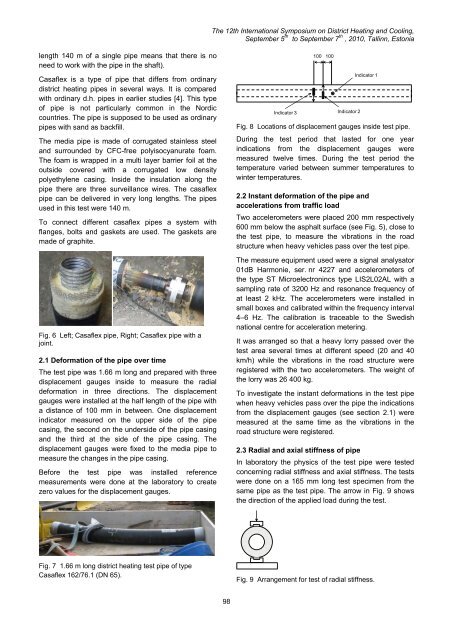
The <str<strong>on</strong>g>12th</str<strong>on</strong>g> <str<strong>on</strong>g>Internati<strong>on</strong>al</str<strong>on</strong>g> <str<strong>on</strong>g>Symposium</str<strong>on</strong>g> <strong>on</strong> <strong>District</strong> <strong>Heating</strong> <strong>and</strong> <strong>Cooling</strong>,September 5 th to September 7 th , 2010, Tallinn, Est<strong>on</strong>ialength 140 m of a single pipe means that there is n<strong>on</strong>eed to work with the pipe in the shaft).Casaflex is a type of pipe that differs from ordinarydistrict heating pipes in several ways. It is comparedwith ordinary d.h. pipes in earlier studies [4]. This typeof pipe is not particularly comm<strong>on</strong> in the Nordiccountries. The pipe is supposed to be used as ordinarypipes with s<strong>and</strong> as backfill.The media pipe is made of corrugated stainless steel<strong>and</strong> surrounded by CFC-free polyisocyanurate foam.The foam is wrapped in a multi layer barrier foil at theoutside covered with a corrugated low densitypolyethylene casing. Inside the insulati<strong>on</strong> al<strong>on</strong>g thepipe there are three surveillance wires. The casaflexpipe can be delivered in very l<strong>on</strong>g lengths. The pipesused in this test were 140 m.To c<strong>on</strong>nect different casaflex pipes a system withflanges, bolts <strong>and</strong> gaskets are used. The gaskets aremade of graphite.Fig. 6 Left; Casaflex pipe, Right; Casaflex pipe with ajoint.2.1 Deformati<strong>on</strong> of the pipe over timeThe test pipe was 1.66 m l<strong>on</strong>g <strong>and</strong> prepared with threedisplacement gauges inside to measure the radialdeformati<strong>on</strong> in three directi<strong>on</strong>s. The displacementgauges were installed at the half length of the pipe witha distance of 100 mm in between. One displacementindicator measured <strong>on</strong> the upper side of the pipecasing, the sec<strong>on</strong>d <strong>on</strong> the underside of the pipe casing<strong>and</strong> the third at the side of the pipe casing. Thedisplacement gauges were fixed to the media pipe tomeasure the changes in the pipe casing.Before the test pipe was installed referencemeasurements were d<strong>on</strong>e at the laboratory to createzero values for the displacement gauges.100100Indicator 3 Indicator 2Indicator 1Fig. 8 Locati<strong>on</strong>s of displacement gauges inside test pipe.During the test period that lasted for <strong>on</strong>e yearindicati<strong>on</strong>s from the displacement gauges weremeasured twelve times. During the test period thetemperature varied between summer temperatures towinter temperatures.2.2 Instant deformati<strong>on</strong> of the pipe <strong>and</strong>accelerati<strong>on</strong>s from traffic loadTwo accelerometers were placed 200 mm respectively600 mm below the asphalt surface (see Fig. 5), close tothe test pipe, to measure the vibrati<strong>on</strong>s in the roadstructure when heavy vehicles pass over the test pipe.The measure equipment used were a signal analysator01dB Harm<strong>on</strong>ie, ser. nr 4227 <strong>and</strong> accelerometers ofthe type ST Microelectr<strong>on</strong>incs type LIS2L02AL with asampling rate of 3200 Hz <strong>and</strong> res<strong>on</strong>ance frequency ofat least 2 kHz. The accelerometers were installed insmall boxes <strong>and</strong> calibrated within the frequency interval4–6 Hz. The calibrati<strong>on</strong> is traceable to the Swedishnati<strong>on</strong>al centre for accelerati<strong>on</strong> metering.It was arranged so that a heavy lorry passed over thetest area several times at different speed (20 <strong>and</strong> 40km/h) while the vibrati<strong>on</strong>s in the road structure wereregistered with the two accelerometers. The weight ofthe lorry was 26 400 kg.To investigate the instant deformati<strong>on</strong>s in the test pipewhen heavy vehicles pass over the pipe the indicati<strong>on</strong>sfrom the displacement gauges (see secti<strong>on</strong> 2.1) weremeasured at the same time as the vibrati<strong>on</strong>s in theroad structure were registered.2.3 Radial <strong>and</strong> axial stiffness of pipeIn laboratory the physics of the test pipe were testedc<strong>on</strong>cerning radial stiffness <strong>and</strong> axial stiffness. The testswere d<strong>on</strong>e <strong>on</strong> a 165 mm l<strong>on</strong>g test specimen from thesame pipe as the test pipe. The arrow in Fig. 9 showsthe directi<strong>on</strong> of the applied load during the test.Fig. 7 1.66 m l<strong>on</strong>g district heating test pipe of typeCasaflex 162/76.1 (DN 65).Fig. 9 Arrangement for test of radial stiffness.98


