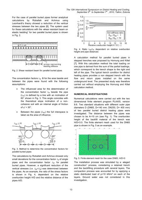
For the case of parallel buried pipes former analyticalcalculati<strong>on</strong>s by Rizkallah <strong>and</strong> Achmus usingLe<strong>on</strong>hardt‘s theory showed a reducti<strong>on</strong> of the verticalstresses between the two pipes [6]. The system usedfor these calculati<strong>on</strong>s with the ―shear resistant beam <strong>on</strong>elastic bedding‖ for two parallel buried pipes is shownin Fig. 2.The <str<strong>on</strong>g>12th</str<strong>on</strong>g> <str<strong>on</strong>g>Internati<strong>on</strong>al</str<strong>on</strong>g> <str<strong>on</strong>g>Symposium</str<strong>on</strong>g> <strong>on</strong> <strong>District</strong> <strong>Heating</strong> <strong>and</strong> <strong>Cooling</strong>,September 5 th to September 7 th , 2010, Tallinn, Est<strong>on</strong>iaFig. 4. Ratio B2/ B dependent <strong>on</strong> relative overburdenheight <strong>and</strong> pipe distancesFig. 2. Shear resistant beam for parallel buried pipesThe c<strong>on</strong>centrati<strong>on</strong> factors B . B for the area beside <strong>and</strong>between the pipes were found with the followingassumpti<strong>on</strong>s:The influenced area for the determinati<strong>on</strong> ofthe c<strong>on</strong>centrati<strong>on</strong> factor B beside the pipe( B1 ) is defined by a line with an inclinati<strong>on</strong> of60° shown in Fig. 3. This angle coincides withthe theoretical slope inclinati<strong>on</strong> of a n<strong>on</strong>cohesivesoil with an internal angle of fricti<strong>on</strong>of ' = 30°.Between the pipes ( B2 ) the full interspace istaken as the area of influence.A calculati<strong>on</strong> method for parallel buried pipes instepped trenches was proposed by Hornung <strong>and</strong> Kittel[7]. With this calculati<strong>on</strong> method the total loading <strong>on</strong><strong>on</strong>e pipe is derived from the sum of the partial loadings,which corresp<strong>on</strong>d to the trench shape to the right <strong>and</strong>left of the pipe. The typical trench c<strong>on</strong>diti<strong>on</strong> for districtheating pipes provides a n<strong>on</strong> stepped trench with theflow <strong>and</strong> return pipes installed <strong>on</strong> the sameunderground level. The presented study was thereforecarried out without employing the Hornung <strong>and</strong> Kittelcalculati<strong>on</strong> method.NUMERICAL INVESTIGATIONSNumerical calculati<strong>on</strong>s were carried out with the twodimensi<strong>on</strong>al finite element program PLAXIS, versi<strong>on</strong>8.6. Two st<strong>and</strong>ard situati<strong>on</strong>s with different outer pipediameters D (DN65, D=140 mm; DN250, D= 400 mm)of two parallel buried district heating pipes wereinvestigated. The distance between the pipes waschosen to be A=10 cm (see Fig. 1). The overburdenheight of the backfill material of the trench wasH/D=3.0. The finite element mesh used for the DN65pipe is shown in Fig. 5 as an example.Fig. 3. Method to determine the c<strong>on</strong>centrati<strong>on</strong> factors forparallel buried pipesThe calculati<strong>on</strong>s by Rizkallah <strong>and</strong> Achmus showed <strong>on</strong>lysmall deviati<strong>on</strong>s for the c<strong>on</strong>centrati<strong>on</strong> factor B of singlepipes <strong>and</strong> the c<strong>on</strong>centrati<strong>on</strong> factor B1 for parallelburied pipes. However, a significant reducti<strong>on</strong> of thevertical stresses (i.e. B2 < B ) was determined betweenthe pipes. As an example, the ratio of the stress factorsis shown in Fig. 4, dependent <strong>on</strong> the relativeoverburden height H/D <strong>and</strong> the relative distance of thepipes A/D.Fig. 5. Finite element mesh for the case DN65, H/D=3The installati<strong>on</strong> process was simulated by a ―stagedc<strong>on</strong>structi<strong>on</strong>‖ process, c<strong>on</strong>sidering a retained trench<strong>and</strong> the backfilling procedure with several layers. Thecompacti<strong>on</strong> process was accounted for by applying astatic distributed load of p=10 kN/m² <strong>on</strong> each of thelayers. Ground water was not c<strong>on</strong>sidered in thisinvestigati<strong>on</strong>.13
S<strong>and</strong> in a medium dense to dense state was assumedas backfill material. The mechanical behaviour of thesoil was modelled with the Mohr-Coulomb c<strong>on</strong>stitutivelaw, which is a linear elastic / ideal plastic materialmodel. The parameters used for the model are shownin Table I.Table I. – Soil parameters used for s<strong>and</strong> in Mohr-Coulombmaterial modelThe <str<strong>on</strong>g>12th</str<strong>on</strong>g> <str<strong>on</strong>g>Internati<strong>on</strong>al</str<strong>on</strong>g> <str<strong>on</strong>g>Symposium</str<strong>on</strong>g> <strong>on</strong> <strong>District</strong> <strong>Heating</strong> <strong>and</strong> <strong>Cooling</strong>,September 5 th to September 7 th , 2010, Tallinn, Est<strong>on</strong>iaDefiniti<strong>on</strong> <strong>and</strong> UnitSizeUnit weight [kN/m³] 18Oedometric Elasticity Modulus E oed [MPa] 70.5Poiss<strong>on</strong>‘s ratio 0.3Internal angle of fricti<strong>on</strong> ‘ [°] 40Angle of dilatancy [°] 10Interface fricti<strong>on</strong> R inter [1] 0.536Between pipe <strong>and</strong> soil, the Coulomb fricti<strong>on</strong> law with aaccording to Eq. (1).tan Rinter *tan 'i (1)Fig. 7. Horiz<strong>on</strong>tal effective stresses h (DN250 pipe,H/D=3)In Fig. 8 the stress c<strong>on</strong>centrati<strong>on</strong> is shown by thedistributi<strong>on</strong> of the radial c<strong>on</strong>tact pressure for the lefth<strong>and</strong>pipe. In the springline area a maximum value of r =21.44 kN/m² for the radial pressure was obtained.Compared with the calculated average radial pressureof r,avg,calc = 18.81 kN/m² the deviati<strong>on</strong> is about 12.2%.In order to keep the model as simple as possible thepipes were assumed to be rigid.In the numerical calculati<strong>on</strong>s the initial soil stress statedue to the soil unit weight was established first. Theinstallati<strong>on</strong> procedure was then simulated <strong>and</strong> theresults were evaluated.In the first model of pipes with an outer diameter ofD=140mm (DN65), no significant stress c<strong>on</strong>centrati<strong>on</strong>between the pipes was observed. The radial c<strong>on</strong>tactpressure obtained for both pipes is shown in Fig. 6.Fig. 8. C<strong>on</strong>tact pressure <strong>on</strong> the left-h<strong>and</strong> DN250 pipe,H/D=3From the DIN EN 13941 regulati<strong>on</strong> the average radialpressure <strong>on</strong> a single buried pipe can be derived for theinvestigated trench c<strong>on</strong>diti<strong>on</strong> according to Eq. (2).r,avg,13941 D 1k * H * 2 2 (2)Fig. 6. C<strong>on</strong>tact pressure <strong>on</strong> the DN65 pipes, H/D=3However, in the sec<strong>on</strong>d numerical model of pipes withan outer diameter of D=400 mm (DN250), a stressc<strong>on</strong>centrati<strong>on</strong> between the pipes was evident. Thedistributi<strong>on</strong> of horiz<strong>on</strong>tal effective stresses acting afterthe installati<strong>on</strong> process is shown in Fig. 7. The stressesare significantly larger between the pipes than beneaththem.In Table II the results of the numerical investigati<strong>on</strong> arecompared to the expected radial pressure from the DINEN 13941 regulati<strong>on</strong>.Table II. – Average c<strong>on</strong>tact pressure r,avg for H/D=3.0DNSingle pipe according toDIN EN 1394165 6.15 kN/m² 7.25 kN/m²Parallel buried pipeaccording to numericalresults250 17.58 kN/m² 18.81 kN/m²Regarding the average radial c<strong>on</strong>tact pressure thedifference between the expected values from the DIN14
- Page 1: 12th Inter
- Page 5 and 6: The 12th I
- Page 7 and 8: The 12th I
- Page 10 and 11: The 12th I
- Page 12 and 13: The 12th I
- Page 16 and 17: The 12th I
- Page 18 and 19: The 12th I
- Page 20 and 21: The 12th I
- Page 22 and 23: The 12th I
- Page 24 and 25: The 12th I
- Page 26 and 27: The 12th I
- Page 28 and 29: The 12th I
- Page 30 and 31: The 12th I
- Page 32 and 33: The 12th I
- Page 34 and 35: The 12th I
- Page 36 and 37: The 12th I
- Page 38 and 39: The 12th I
- Page 40 and 41: The 12th I
- Page 42 and 43: The 12th I
- Page 44 and 45: The 12th I
- Page 46 and 47: The 12th I
- Page 48 and 49: The 12th I
- Page 50 and 51: The 12th I
- Page 52 and 53: The 12th I
- Page 54 and 55: The 12th I
- Page 56 and 57: The 12th I
- Page 58 and 59: The 12th I
- Page 60 and 61: The 12th I
- Page 62 and 63: The 12th I
- Page 64 and 65:
The 12th I
- Page 66 and 67:
The 12th I
- Page 68 and 69:
The 12th I
- Page 70 and 71:
The 12th I
- Page 72 and 73:
The 12th I
- Page 74 and 75:
The 12th I
- Page 76 and 77:
The 12th I
- Page 78 and 79:
The 12th I
- Page 80 and 81:
The 12th I
- Page 82 and 83:
The 12th I
- Page 84 and 85:
The 12th I
- Page 86 and 87:
The 12th I
- Page 88 and 89:
The 12th I
- Page 90 and 91:
The 12th I
- Page 92 and 93:
The 12th I
- Page 94 and 95:
The 12th I
- Page 96 and 97:
The 12th I
- Page 98 and 99:
the street the more shallow the sha
- Page 100 and 101:
The 12th I
- Page 102 and 103:
The 12th I
- Page 104 and 105:
The 12th I
- Page 106 and 107:
The 12th I
- Page 108 and 109:
The 12th I
- Page 110 and 111:
P-1P-4P-9P-7E-5P-14P-8The 1
- Page 112 and 113:
The 12th I
- Page 114 and 115:
The 12th I
- Page 116 and 117:
The 12th I
- Page 118 and 119:
The 12th I
- Page 120 and 121:
The 12th I
- Page 122 and 123:
The 12th I
- Page 124 and 125:
The 12th I
- Page 126 and 127:
The 12th I
- Page 128 and 129:
The 12th I
- Page 130 and 131:
The 12th I
- Page 132 and 133:
The 12th I
- Page 134 and 135:
The 12th I
- Page 136 and 137:
The 12th I
- Page 138 and 139:
to heating costs of 14,5 ct/kWh. Th
- Page 140 and 141:
The 12th I
- Page 142 and 143:
The 12th I
- Page 144 and 145:
The 12th I
- Page 146 and 147:
The 12th I
- Page 148 and 149:
academic access is facilitated as t
- Page 150 and 151:
The 12th I
- Page 152 and 153:
The 12th I
- Page 154 and 155:
The 12th I
- Page 156 and 157:
The 12th I
- Page 158 and 159:
The 12th I
- Page 160 and 161:
The 12th I
- Page 162 and 163:
1. CHP system operation in A2. Ther
- Page 164 and 165:
The 12th I
- Page 166 and 167:
is covered by operating HOB. In oth
- Page 168 and 169:
The 12th I
- Page 170 and 171:
The 12th I
- Page 172 and 173:
The 12th I
- Page 174 and 175:
The 12th I
- Page 176 and 177:
The 12th I
- Page 178 and 179:
The 12th I
- Page 180 and 181:
The 12th I
- Page 182 and 183:
The 12th I
- Page 184 and 185:
The 12th I
- Page 186 and 187:
The 12th I
- Page 188 and 189:
The 12th I
- Page 190 and 191:
The 12th I
- Page 192 and 193:
The 12th I
- Page 194 and 195:
The 12th I
- Page 196 and 197:
produce heat and electricity. Fluct
- Page 198 and 199:
The 12th I
- Page 200 and 201:
The 12th I
- Page 202 and 203:
The 12th I
- Page 204 and 205:
The 12th I
- Page 206 and 207:
The 12th I
- Page 208 and 209:
The 12th I
- Page 210 and 211:
To assure that the temperatures mea
- Page 212 and 213:
The 12th I
- Page 214 and 215:
The 12th I
- Page 216 and 217:
The 12th I
- Page 218 and 219:
The 12th I
- Page 220 and 221:
production and provide for marginal
- Page 222 and 223:
The 12th I
- Page 224 and 225:
The 12th I
- Page 226 and 227:
The 12th I
- Page 228 and 229:
The 12th I
- Page 230 and 231:
The 12th I
- Page 232 and 233:
The 12th I
- Page 234 and 235:
The 12th I
- Page 236 and 237:
The 12th I
- Page 238 and 239:
The 12th I
- Page 240 and 241:
The 12th I
- Page 242 and 243:
In addition, it can also be observe
- Page 244 and 245:
The 12th I
- Page 246 and 247:
owner is normally only interested i
- Page 248 and 249:
The 12th I
- Page 250 and 251:
The 12th I
- Page 252 and 253:
The 12th I
- Page 254 and 255:
The 12th I
- Page 256 and 257:
The 12th I
- Page 258 and 259:
The 12th I
- Page 260 and 261:
The 12th I
- Page 262 and 263:
The 12th I
- Page 264 and 265:
The 12th I
- Page 266 and 267:
The 12th I
- Page 268 and 269:
The 12th I
- Page 270 and 271:
The 12th I
- Page 272 and 273:
The 12th I
- Page 274 and 275:
The 12th I
- Page 276 and 277:
The 12th I
- Page 278 and 279:
The 12th I
- Page 280 and 281:
The 12th I
- Page 282 and 283:
The 12th I
- Page 284 and 285:
The 12th I
- Page 286 and 287:
The 12th I
- Page 288 and 289:
The 12th I
- Page 290 and 291:
Stockholm district heating system a
- Page 292 and 293:
The 12th I
- Page 294 and 295:
The 12th I
- Page 296 and 297:
The 12th I
- Page 298 and 299:
The 12th I
- Page 300 and 301:
The 12th I
- Page 302 and 303:
The 12th I
- Page 304 and 305:
The 12th I
- Page 306 and 307:
The 12th I
- Page 308 and 309:
The 12th I
- Page 310 and 311:
The 12th I
- Page 312 and 313:
The 12th I
- Page 314 and 315:
The values presented do of course l
- Page 316 and 317:
The 12th I
- Page 318 and 319:
The 12th I
- Page 320 and 321:
The 12th I
- Page 322 and 323:
The 12th I
- Page 324 and 325:
The 12th I
- Page 326:
The 12th I