The <str<strong>on</strong>g>12th</str<strong>on</strong>g> <str<strong>on</strong>g>Internati<strong>on</strong>al</str<strong>on</strong>g> <str<strong>on</strong>g>Symposium</str<strong>on</strong>g> <strong>on</strong> <strong>District</strong> <strong>Heating</strong> <strong>and</strong> <strong>Cooling</strong>,September 5 th to September 7 th , 2010, Tallinn, Est<strong>on</strong>ia1200(1) ST.PUR.PE Ref (2) PB as measured std eng.1000Pipe Length [m]800600400200Fig. 12, Pressure drop steel network with increasedservice pipe flowThere is not a lot of difference between both graphs inFig. 10 <strong>and</strong> Fig. 12. The reas<strong>on</strong> for this is that thedesign maximum fluid velocity is rather low for steel.This may prove different for the PB network, which isdesigned with smaller diameters in the periphery. SeeFig. 13, which can be compared to Fig. 11.The graph in Fig. 13 indeed shows an increasedpressure drop in the service pipes c<strong>on</strong>necting thehouses, when the flow in those pipes is artificiallyincreased to 100% of the installed power. However, thetotal pressure drop stays within the same limits as doesthe steel network under similar c<strong>on</strong>diti<strong>on</strong>s (Fig. 12).016 20 25 32 40 50 63 75 90 110Nominal diameter [mm]Fig. 14, Pipe length histogram Steel <strong>and</strong> PBAs a result of the use of smaller diameters with PB, thedistributi<strong>on</strong> of pipe lengths generally shifts to the left inthe pipe histogram. As heat loss increases withdiameter (see Fig. 8) this should have a positive effect<strong>on</strong> the total distributi<strong>on</strong> system heat loss.This shift to the left may be taken <strong>on</strong>e step further,since the wall thickness of the smallest PB mediumpipes currently is chosen a bit larger than the strengthclass (SDR11) requires. This is d<strong>on</strong>e for ease ofinstallati<strong>on</strong>. If the thickness of these pipes is chosen nolarger than SDR11, there is a slight additi<strong>on</strong>al shift tothe left, see Fig. 15.(1) ST.PUR.PE Ref (2) PB as measured std eng.(3) PB impr. Fresh all SDR1112001000Pipe Length [m]800600400200Fig. 13, Pressure drop PB network with increased servicepipe flowThe result of both design calculati<strong>on</strong>s is plotted inFig. 14, steel in red <strong>and</strong> PB in green.016 20 25 32 40 50 63 75 90 110Nominal diameter [mm]Fig. 15, Pipe length histogram steel, PB <strong>and</strong> PB SDR11networks315
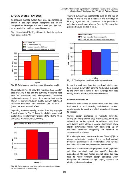
The <str<strong>on</strong>g>12th</str<strong>on</strong>g> <str<strong>on</strong>g>Internati<strong>on</strong>al</str<strong>on</strong>g> <str<strong>on</strong>g>Symposium</str<strong>on</strong>g> <strong>on</strong> <strong>District</strong> <strong>Heating</strong> <strong>and</strong> <strong>Cooling</strong>,September 5 th to September 7 th , 2010, Tallinn, Est<strong>on</strong>ia6. TOTAL SYSTEM HEAT LOSSTo calculate the total system heat loss, pipe lengths asshown in the pipe length histograms are to bemultiplied by the respective heat losses per pipe pair,as shown in the heat loss value histograms.Fig. 15 ―multiplied‖ by Fig. 6 leads to the total systemheat losses in Fig. 16.Heat Loss [kW]80.070.060.050.040.030.020.010.00.0ST.PUR.PE RefPB as measured std eng.PB increased insulati<strong>on</strong> thicknessPB increased insulati<strong>on</strong> thickness all SDR11system [-]Fig. 16, Total system heat loss, current insulati<strong>on</strong> qualityThe graphs in Fig. 16 show the reference heat loss forsteel-PUR-PE in red <strong>and</strong> the currently measured heatloss for PB-PE-PE with n<strong>on</strong>-optimized insulati<strong>on</strong>thickness in orange. In green, total system heat loss isshown for current insulati<strong>on</strong> quality but with optimizedinsulati<strong>on</strong> thickness. The exclusive use of SDR11(blue) has a rather small effect.Improving insulati<strong>on</strong> quality, as described in paragraph5 <strong>and</strong> shown in Fig. 7, leads to slightly lower totalsystem heat loss for freshly produced PB-PE-PE whencompared to the reference, see Fig. 17.Heat Loss [kW]60.050.040.030.020.010.00.0ST.PUR.PE RefPB impr. insulati<strong>on</strong> thickness/qualitysystem [-]There is currently no experimental data <strong>on</strong> the rate ofageing of PB-PE-PE as a result of the exchange ofblowing agent with air. However, it is possible tocalculate a worst case situati<strong>on</strong> (see fig. 18), using thepredicted values plotted in fig. 8.Heat Loss [kW]70.060.050.040.030.020.010.00.0ST.PUR.PE RefPB impr. insulati<strong>on</strong> thickness/qualityPB impr. Insulati<strong>on</strong> thickness/quality degassedsystem [-]Fig. 18, Total system heat loss, including worst caseIn practice <strong>and</strong> over time, the predicted total systemheat loss will slowly shift from the fresh value in purpleto the worst case value in blue. Average heat lossduring lifetime will be somewhere in-between.FUTURE RESEARCHHydraulic calculati<strong>on</strong>s in combinati<strong>on</strong> with insulati<strong>on</strong>thickness form an interesting optimizati<strong>on</strong> problem:what diameter to select <strong>and</strong> which insulati<strong>on</strong> thicknessto choose?Current design strategies for hydraulic networks,aiming at linear pressure drop with distance, seem tooadventitious to be optimal. In additi<strong>on</strong>, heat losscalculati<strong>on</strong>s using st<strong>and</strong>ard casing dimensi<strong>on</strong>s showrapidly diminishing yields with each step up ininsulati<strong>on</strong> thickness, suggesting the optimum issomewhere in-between.First attempts have been made to use Pipelab [6] in adouble optimizati<strong>on</strong> routine, trying to find optimalhydraulic performance in combinati<strong>on</strong> with optimalinsulati<strong>on</strong> thickness distributi<strong>on</strong> over the network.Given the specific hydraulic properties of PB (high fluidvelocities permitted) <strong>and</strong> the specific insulati<strong>on</strong>properties of PE foam (better at small size), this maylead to rather different design strategies whencompared to c<strong>on</strong>venti<strong>on</strong>al rigid piping systems fordistrict heating <strong>and</strong> cooling.Fig. 17, Total system heat loss, reference <strong>and</strong> predicti<strong>on</strong>for improved insulati<strong>on</strong> quality316
- Page 1:
12th Inter
- Page 5 and 6:
The 12th I
- Page 7 and 8:
The 12th I
- Page 10 and 11:
The 12th I
- Page 12 and 13:
The 12th I
- Page 14 and 15:
For the case of parallel buried pip
- Page 16 and 17:
The 12th I
- Page 18 and 19:
The 12th I
- Page 20 and 21:
The 12th I
- Page 22 and 23:
The 12th I
- Page 24 and 25:
The 12th I
- Page 26 and 27:
The 12th I
- Page 28 and 29:
The 12th I
- Page 30 and 31:
The 12th I
- Page 32 and 33:
The 12th I
- Page 34 and 35:
The 12th I
- Page 36 and 37:
The 12th I
- Page 38 and 39:
The 12th I
- Page 40 and 41:
The 12th I
- Page 42 and 43:
The 12th I
- Page 44 and 45:
The 12th I
- Page 46 and 47:
The 12th I
- Page 48 and 49:
The 12th I
- Page 50 and 51:
The 12th I
- Page 52 and 53:
The 12th I
- Page 54 and 55:
The 12th I
- Page 56 and 57:
The 12th I
- Page 58 and 59:
The 12th I
- Page 60 and 61:
The 12th I
- Page 62 and 63:
The 12th I
- Page 64 and 65:
The 12th I
- Page 66 and 67:
The 12th I
- Page 68 and 69:
The 12th I
- Page 70 and 71:
The 12th I
- Page 72 and 73:
The 12th I
- Page 74 and 75:
The 12th I
- Page 76 and 77:
The 12th I
- Page 78 and 79:
The 12th I
- Page 80 and 81:
The 12th I
- Page 82 and 83:
The 12th I
- Page 84 and 85:
The 12th I
- Page 86 and 87:
The 12th I
- Page 88 and 89:
The 12th I
- Page 90 and 91:
The 12th I
- Page 92 and 93:
The 12th I
- Page 94 and 95:
The 12th I
- Page 96 and 97:
The 12th I
- Page 98 and 99:
the street the more shallow the sha
- Page 100 and 101:
The 12th I
- Page 102 and 103:
The 12th I
- Page 104 and 105:
The 12th I
- Page 106 and 107:
The 12th I
- Page 108 and 109:
The 12th I
- Page 110 and 111:
P-1P-4P-9P-7E-5P-14P-8The 1
- Page 112 and 113:
The 12th I
- Page 114 and 115:
The 12th I
- Page 116 and 117:
The 12th I
- Page 118 and 119:
The 12th I
- Page 120 and 121:
The 12th I
- Page 122 and 123:
The 12th I
- Page 124 and 125:
The 12th I
- Page 126 and 127:
The 12th I
- Page 128 and 129:
The 12th I
- Page 130 and 131:
The 12th I
- Page 132 and 133:
The 12th I
- Page 134 and 135:
The 12th I
- Page 136 and 137:
The 12th I
- Page 138 and 139:
to heating costs of 14,5 ct/kWh. Th
- Page 140 and 141:
The 12th I
- Page 142 and 143:
The 12th I
- Page 144 and 145:
The 12th I
- Page 146 and 147:
The 12th I
- Page 148 and 149:
academic access is facilitated as t
- Page 150 and 151:
The 12th I
- Page 152 and 153:
The 12th I
- Page 154 and 155:
The 12th I
- Page 156 and 157:
The 12th I
- Page 158 and 159:
The 12th I
- Page 160 and 161:
The 12th I
- Page 162 and 163:
1. CHP system operation in A2. Ther
- Page 164 and 165:
The 12th I
- Page 166 and 167:
is covered by operating HOB. In oth
- Page 168 and 169:
The 12th I
- Page 170 and 171:
The 12th I
- Page 172 and 173:
The 12th I
- Page 174 and 175:
The 12th I
- Page 176 and 177:
The 12th I
- Page 178 and 179:
The 12th I
- Page 180 and 181:
The 12th I
- Page 182 and 183:
The 12th I
- Page 184 and 185:
The 12th I
- Page 186 and 187:
The 12th I
- Page 188 and 189:
The 12th I
- Page 190 and 191:
The 12th I
- Page 192 and 193:
The 12th I
- Page 194 and 195:
The 12th I
- Page 196 and 197:
produce heat and electricity. Fluct
- Page 198 and 199:
The 12th I
- Page 200 and 201:
The 12th I
- Page 202 and 203:
The 12th I
- Page 204 and 205:
The 12th I
- Page 206 and 207:
The 12th I
- Page 208 and 209:
The 12th I
- Page 210 and 211:
To assure that the temperatures mea
- Page 212 and 213:
The 12th I
- Page 214 and 215:
The 12th I
- Page 216 and 217:
The 12th I
- Page 218 and 219:
The 12th I
- Page 220 and 221:
production and provide for marginal
- Page 222 and 223:
The 12th I
- Page 224 and 225:
The 12th I
- Page 226 and 227:
The 12th I
- Page 228 and 229:
The 12th I
- Page 230 and 231:
The 12th I
- Page 232 and 233:
The 12th I
- Page 234 and 235:
The 12th I
- Page 236 and 237:
The 12th I
- Page 238 and 239:
The 12th I
- Page 240 and 241:
The 12th I
- Page 242 and 243:
In addition, it can also be observe
- Page 244 and 245:
The 12th I
- Page 246 and 247:
owner is normally only interested i
- Page 248 and 249:
The 12th I
- Page 250 and 251:
The 12th I
- Page 252 and 253:
The 12th I
- Page 254 and 255:
The 12th I
- Page 256 and 257:
The 12th I
- Page 258 and 259:
The 12th I
- Page 260 and 261:
The 12th I
- Page 262 and 263:
The 12th I
- Page 264 and 265:
The 12th I
- Page 266 and 267: The 12th I
- Page 268 and 269: The 12th I
- Page 270 and 271: The 12th I
- Page 272 and 273: The 12th I
- Page 274 and 275: The 12th I
- Page 276 and 277: The 12th I
- Page 278 and 279: The 12th I
- Page 280 and 281: The 12th I
- Page 282 and 283: The 12th I
- Page 284 and 285: The 12th I
- Page 286 and 287: The 12th I
- Page 288 and 289: The 12th I
- Page 290 and 291: Stockholm district heating system a
- Page 292 and 293: The 12th I
- Page 294 and 295: The 12th I
- Page 296 and 297: The 12th I
- Page 298 and 299: The 12th I
- Page 300 and 301: The 12th I
- Page 302 and 303: The 12th I
- Page 304 and 305: The 12th I
- Page 306 and 307: The 12th I
- Page 308 and 309: The 12th I
- Page 310 and 311: The 12th I
- Page 312 and 313: The 12th I
- Page 314 and 315: The values presented do of course l
- Page 318 and 319: The 12th I
- Page 320 and 321: The 12th I
- Page 322 and 323: The 12th I
- Page 324 and 325: The 12th I
- Page 326: The 12th I