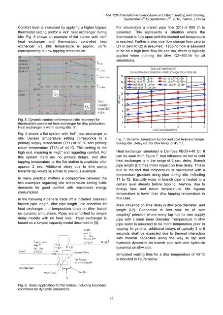
The <str<strong>on</strong>g>12th</str<strong>on</strong>g> <str<strong>on</strong>g>Internati<strong>on</strong>al</str<strong>on</strong>g> <str<strong>on</strong>g>Symposium</str<strong>on</strong>g> <strong>on</strong> <strong>District</strong> <strong>Heating</strong> <strong>and</strong> <strong>Cooling</strong>,September 5 th to September 7 th , 2010, Tallinn, Est<strong>on</strong>iaComfort level is increased by applying a higher bypassthermostat setting <strong>and</strong>/or a ―hot‖ heat exchanger duringidle. Fig. 5 shows an example of flat stati<strong>on</strong> with ―hot‖heat exchanger <strong>and</strong> thermostatic c<strong>on</strong>trolled heatexchanger [7]. Idle temperature is approx. 50 °Ccorresp<strong>on</strong>ding to dhw tapping temperature.For simulati<strong>on</strong>s a branch pipe flow (Q1) of 800 l/h isassumed. This represents a situati<strong>on</strong> where thethermostat is fully open until the desired set temperatureis reached. Further a step vice flow change from zero toQ1 or zero to Q2 is assumed. Tapping flow is assumedto be <strong>on</strong> a high level flow for <strong>on</strong>e tap, which is typicallyapplied when opening the dhw. Q2=400 l/h for allsimulati<strong>on</strong>s.161412Delay until reaching 45°CL2=5m & 10m (internal ø10mm) - Heat Exchanger hot & cold at idlehot - dt at T2 - L2=5mhot - dt at T4 - L2=5mcold - dt at T3 - L2=5mcold - dt at T4 - L2=10mhot - dt at T3 - L2=5mhot - dt at T4 - L2=10mcold - dt at T4 - L2=5mdT [sec]10864Fig. 5. Dynamic c<strong>on</strong>trol performance (idle recovery) forthermostatic c<strong>on</strong>trolled heat exchanger for dhw producti<strong>on</strong>.Heat exchanger is warm during idle. [7]Fig. 5 shows a flat system with ―hot‖ heat exchanger atidle. Bypass temperature setting corresp<strong>on</strong>ds to aprimary supply temperature (T11) of 58 °C <strong>and</strong> primaryreturn temperature (T12) of 44 °C. This setting is thehigh end, meaning in ―high‖ end regarding comfort. Forthis system there are no primary delays, <strong>and</strong> dhwtapping temperature at the flat stati<strong>on</strong> is available afterapprox. 2 sec. Additi<strong>on</strong>al delay due to dhw pipingtowards tap would be similar to previous example.In many practical matters a compromise between thetwo examples regarding idle temperature setting fulfilsdem<strong>and</strong>s for good comfort with reas<strong>on</strong>able energyc<strong>on</strong>sumpti<strong>on</strong>.In the following a general trade off is included betweenbranch pipe length, dhw pipe length, idle c<strong>on</strong>diti<strong>on</strong> forheat exchanger <strong>and</strong> temperature delay <strong>on</strong> dhw, based<strong>on</strong> dynamic simulati<strong>on</strong>s. Pipes are simplified by simpledelay models with no heat loss. Heat exchanger isbased <strong>on</strong> a lumped capacity model described in [5].200 1 2 3 4 5 6L1 [m] (internal ø20mm)Fig. 7. Dynamic simulati<strong>on</strong> for hot <strong>and</strong> cold heat exchangerduring idle. Delay (dt) for dhw temp. of 45 °C.Heat exchanger simulated is Danfoss XB06H-40 [6]. Itcan be seen from figure 7, that influence <strong>on</strong> hot or coldheat exchanger is in the range of 2 sec. delay. Branchpipe length (L1) has minor impact <strong>on</strong> time delay. This isdue to the fact that temperature is maintained with atemperature gradient al<strong>on</strong>g pipe during idle, reflectingT1 to T2. Basically water in branch pipe is heated to acertain level already before tapping. Anyhow, due toenergy loss <strong>and</strong> return temperature, idle bypasstemperature is lower than dhw tapping temperature inthis case.Main influence <strong>on</strong> time delay is dhw pipe diameter <strong>and</strong>length (L2). C<strong>on</strong>necti<strong>on</strong> in flats shall be of ―starcoupling‖ principle where every tap has its own supplypipe with a small inner diameter. Temperature in dhwpipe water is assumed to be room temperature prior totapping. In general, additi<strong>on</strong>al delays of typically 3 to 6sec<strong>on</strong>ds shall be expected due to thermal interacti<strong>on</strong>with thermal capacities al<strong>on</strong>g the way to tap <strong>and</strong>hydraulic dynamics <strong>on</strong> branch pipe side <strong>and</strong> hydraulicdynamics <strong>on</strong> dhw side.Simulated waiting time for a dhw temperature of 40 °Cis included in figure below:Fig. 6. Basic applicati<strong>on</strong> for flat stati<strong>on</strong>, including boundaryc<strong>on</strong>diti<strong>on</strong>s for dynamic simulati<strong>on</strong>s.19
The <str<strong>on</strong>g>12th</str<strong>on</strong>g> <str<strong>on</strong>g>Internati<strong>on</strong>al</str<strong>on</strong>g> <str<strong>on</strong>g>Symposium</str<strong>on</strong>g> <strong>on</strong> <strong>District</strong> <strong>Heating</strong> <strong>and</strong> <strong>Cooling</strong>,September 5 th to September 7 th , 2010, Tallinn, Est<strong>on</strong>iadT [sec]1614121086420Delay until reaching 40°CL2=5m & 10m (internal ø10mm) - Heat Exchanger hot & cold at idlehot - dt at T4 - l"=5mcold - dt at T4 - l2=5mcold - dt at T4 - L2=10mhot - dt at T4 - L2=10mcold - dt at T3 - L2=5m0 1 2 3 4 5 6L1 [m] (internal ø20mm)Fig. 7. Dynamic simulati<strong>on</strong> results for hot <strong>and</strong> cold heatexchanger during idle. Delay (dt) for dhw temp. of40 °C.First of all it can be seen that time delay for reaching40 °C at tap is <strong>on</strong>ly a bit shorter than reaching 45 °C.This is due to the fact that the T4 temperature profilehas an almost step vice nature, i.e. if temperature goesup after the dhw pipe is flushed through, it goes almostlike a step.Different dhw c<strong>on</strong>trollers have different performanceregarding time delay. In case of pure proporti<strong>on</strong>alc<strong>on</strong>trol for dhw system, time delay is l<strong>on</strong>ger at part load.This is because primary flow is proporti<strong>on</strong>al tosec<strong>on</strong>dary flow, <strong>and</strong> the lower the flow the l<strong>on</strong>ger thewaiting time. Looking at the example for Q1=800l/h,Q2=400 l/h, L1=4 m, L2=5 m then time delay (dt) at T4is 6.9 sec to reach 45 °C dhw temperature. In case ofproporti<strong>on</strong>al c<strong>on</strong>troller with parameters Q1=400 l/h,Q2=400 l/h, L1=4m, L2=5 m then dt=11.0 sec to reach45 °C. This has c<strong>on</strong>siderable effect <strong>on</strong> time delay as L1gets l<strong>on</strong>ger. In case of a thermostatically c<strong>on</strong>trolled dhwsystem or a combinati<strong>on</strong> of a thermostatically <strong>and</strong>proporti<strong>on</strong>ally c<strong>on</strong>trolled dhw system, time delay isshorter because no matter how small tapping is, as l<strong>on</strong>gas the desired set point temperature is not reached, theprimary valve will be fully or almost fully open resultingin high primary flow. Regarding delay to reach a dhwtemperature of 40 °C this is <strong>on</strong>ly related to dhw pipedimensi<strong>on</strong> since 40 °C is the bypass temperature if heatexchanger is hot during idle. In case the heat exchangeris cold during idle, then this introduces an additi<strong>on</strong>altime delay as described above. In all cases, time delayis dependent <strong>on</strong> dhw flow, resulting in delay in the dhwpipe.Hygienic c<strong>on</strong>siderati<strong>on</strong>sLegi<strong>on</strong>ella is a well-known bacterial risk for dhwsystems. Normally it is not the questi<strong>on</strong> whetherLegi<strong>on</strong>ella is present in the dhw system or not, butrather Legi<strong>on</strong>ella bacteria c<strong>on</strong>centrati<strong>on</strong> in the dhw.Facts influencing <strong>on</strong> potential for Legi<strong>on</strong>ellac<strong>on</strong>centrati<strong>on</strong> growth are dhw temperature, exchangerate of hot water in distributi<strong>on</strong> pipes, <strong>and</strong> volume ofdhw water in the entire hot system. Also other factorsare influencing, e.g. systematic cleaning of showeroutlets, but this will be not addressed to here, since theeffect is similar for c<strong>on</strong>cepts compared.Comparing volumes of dhw in pipes for c<strong>on</strong>cepts, theflats stati<strong>on</strong> soluti<strong>on</strong> has significantly lower volumecompared to the traditi<strong>on</strong>al system. Furthermore dhwpipes should be ―star‖ c<strong>on</strong>nected, meaning <strong>on</strong>e small(diameter) pipe from the flat stati<strong>on</strong> to each individualhot tap. This eliminates problematic dead end or lowflow areas.Typically volume of heat exchanger is 0.25 to 0.50 litre.Typical dhw pipe volume is 0.10 l/m, equal to 1.0 litre for10 m pipe. In total this is a volume of 1.5 to 2 litrepr. flat. The comparable centrally placed dhw systemwith dhw distributi<strong>on</strong> will have a volume of 5–7 litre pr.flat. By installing a dhw storage tank this will increasesignificantly. The German DVGW regulati<strong>on</strong>s states thatheating dhw up to 60 °C, due to e.g. Legi<strong>on</strong>ella, is notrequired if volumes of heat exchanger or volume of dhwpipes is less than 3 litres [8]. Based <strong>on</strong> those physicalc<strong>on</strong>cept differences Legi<strong>on</strong>ella bacteria risk is reducedfor the flat stati<strong>on</strong> c<strong>on</strong>cept.Future energy supply/dem<strong>and</strong> perspectiveOne important challenge for DH is to c<strong>on</strong>vert to 4thgenerati<strong>on</strong> DH systems. Intenti<strong>on</strong> is to realise efficientDH systems for urban areas where heat dem<strong>and</strong>s willdecrease due to modernisati<strong>on</strong> <strong>and</strong> new building energysaving codes. In this c<strong>on</strong>text <strong>on</strong>e way to go is to reducetemperatures in DH networks [9]/[10]. This allows forcost effective geothermal sources as well as otherrenewable low temperature sources. For dhw, normaltemperature level is 45 to 60°, where highertemperatures typically are based <strong>on</strong> c<strong>on</strong>siderati<strong>on</strong>stowards Legi<strong>on</strong>ella. A way to reduce temperature levelsin DH networks is to set dhw temperature at 45 °C. Bythis a primary temperature at sub stati<strong>on</strong> of 50 to 55 °Cwill be sufficient. A prec<strong>on</strong>diti<strong>on</strong> for this is to use heatexchangers for dhw producti<strong>on</strong>, like the flat stati<strong>on</strong>c<strong>on</strong>cept.CONCLUSIONThe two pipe flat stati<strong>on</strong> c<strong>on</strong>cepts, c<strong>on</strong>sisting ofdecentralised instantaneous dhw producti<strong>on</strong>, open thepossibility of reducing general DH net work temperature,which for the future will be even more relevant due todecreasing building heat dem<strong>and</strong> <strong>and</strong> increasedavailability of renewable energy. For building owners,the investigated case shows that the flat stati<strong>on</strong> c<strong>on</strong>ceptis <strong>on</strong> brake-even investment level compared to20
- Page 1: 12th Inter
- Page 5 and 6: The 12th I
- Page 7 and 8: The 12th I
- Page 10 and 11: The 12th I
- Page 12 and 13: The 12th I
- Page 14 and 15: For the case of parallel buried pip
- Page 16 and 17: The 12th I
- Page 18 and 19: The 12th I
- Page 22 and 23: The 12th I
- Page 24 and 25: The 12th I
- Page 26 and 27: The 12th I
- Page 28 and 29: The 12th I
- Page 30 and 31: The 12th I
- Page 32 and 33: The 12th I
- Page 34 and 35: The 12th I
- Page 36 and 37: The 12th I
- Page 38 and 39: The 12th I
- Page 40 and 41: The 12th I
- Page 42 and 43: The 12th I
- Page 44 and 45: The 12th I
- Page 46 and 47: The 12th I
- Page 48 and 49: The 12th I
- Page 50 and 51: The 12th I
- Page 52 and 53: The 12th I
- Page 54 and 55: The 12th I
- Page 56 and 57: The 12th I
- Page 58 and 59: The 12th I
- Page 60 and 61: The 12th I
- Page 62 and 63: The 12th I
- Page 64 and 65: The 12th I
- Page 66 and 67: The 12th I
- Page 68 and 69: The 12th I
- Page 70 and 71:
The 12th I
- Page 72 and 73:
The 12th I
- Page 74 and 75:
The 12th I
- Page 76 and 77:
The 12th I
- Page 78 and 79:
The 12th I
- Page 80 and 81:
The 12th I
- Page 82 and 83:
The 12th I
- Page 84 and 85:
The 12th I
- Page 86 and 87:
The 12th I
- Page 88 and 89:
The 12th I
- Page 90 and 91:
The 12th I
- Page 92 and 93:
The 12th I
- Page 94 and 95:
The 12th I
- Page 96 and 97:
The 12th I
- Page 98 and 99:
the street the more shallow the sha
- Page 100 and 101:
The 12th I
- Page 102 and 103:
The 12th I
- Page 104 and 105:
The 12th I
- Page 106 and 107:
The 12th I
- Page 108 and 109:
The 12th I
- Page 110 and 111:
P-1P-4P-9P-7E-5P-14P-8The 1
- Page 112 and 113:
The 12th I
- Page 114 and 115:
The 12th I
- Page 116 and 117:
The 12th I
- Page 118 and 119:
The 12th I
- Page 120 and 121:
The 12th I
- Page 122 and 123:
The 12th I
- Page 124 and 125:
The 12th I
- Page 126 and 127:
The 12th I
- Page 128 and 129:
The 12th I
- Page 130 and 131:
The 12th I
- Page 132 and 133:
The 12th I
- Page 134 and 135:
The 12th I
- Page 136 and 137:
The 12th I
- Page 138 and 139:
to heating costs of 14,5 ct/kWh. Th
- Page 140 and 141:
The 12th I
- Page 142 and 143:
The 12th I
- Page 144 and 145:
The 12th I
- Page 146 and 147:
The 12th I
- Page 148 and 149:
academic access is facilitated as t
- Page 150 and 151:
The 12th I
- Page 152 and 153:
The 12th I
- Page 154 and 155:
The 12th I
- Page 156 and 157:
The 12th I
- Page 158 and 159:
The 12th I
- Page 160 and 161:
The 12th I
- Page 162 and 163:
1. CHP system operation in A2. Ther
- Page 164 and 165:
The 12th I
- Page 166 and 167:
is covered by operating HOB. In oth
- Page 168 and 169:
The 12th I
- Page 170 and 171:
The 12th I
- Page 172 and 173:
The 12th I
- Page 174 and 175:
The 12th I
- Page 176 and 177:
The 12th I
- Page 178 and 179:
The 12th I
- Page 180 and 181:
The 12th I
- Page 182 and 183:
The 12th I
- Page 184 and 185:
The 12th I
- Page 186 and 187:
The 12th I
- Page 188 and 189:
The 12th I
- Page 190 and 191:
The 12th I
- Page 192 and 193:
The 12th I
- Page 194 and 195:
The 12th I
- Page 196 and 197:
produce heat and electricity. Fluct
- Page 198 and 199:
The 12th I
- Page 200 and 201:
The 12th I
- Page 202 and 203:
The 12th I
- Page 204 and 205:
The 12th I
- Page 206 and 207:
The 12th I
- Page 208 and 209:
The 12th I
- Page 210 and 211:
To assure that the temperatures mea
- Page 212 and 213:
The 12th I
- Page 214 and 215:
The 12th I
- Page 216 and 217:
The 12th I
- Page 218 and 219:
The 12th I
- Page 220 and 221:
production and provide for marginal
- Page 222 and 223:
The 12th I
- Page 224 and 225:
The 12th I
- Page 226 and 227:
The 12th I
- Page 228 and 229:
The 12th I
- Page 230 and 231:
The 12th I
- Page 232 and 233:
The 12th I
- Page 234 and 235:
The 12th I
- Page 236 and 237:
The 12th I
- Page 238 and 239:
The 12th I
- Page 240 and 241:
The 12th I
- Page 242 and 243:
In addition, it can also be observe
- Page 244 and 245:
The 12th I
- Page 246 and 247:
owner is normally only interested i
- Page 248 and 249:
The 12th I
- Page 250 and 251:
The 12th I
- Page 252 and 253:
The 12th I
- Page 254 and 255:
The 12th I
- Page 256 and 257:
The 12th I
- Page 258 and 259:
The 12th I
- Page 260 and 261:
The 12th I
- Page 262 and 263:
The 12th I
- Page 264 and 265:
The 12th I
- Page 266 and 267:
The 12th I
- Page 268 and 269:
The 12th I
- Page 270 and 271:
The 12th I
- Page 272 and 273:
The 12th I
- Page 274 and 275:
The 12th I
- Page 276 and 277:
The 12th I
- Page 278 and 279:
The 12th I
- Page 280 and 281:
The 12th I
- Page 282 and 283:
The 12th I
- Page 284 and 285:
The 12th I
- Page 286 and 287:
The 12th I
- Page 288 and 289:
The 12th I
- Page 290 and 291:
Stockholm district heating system a
- Page 292 and 293:
The 12th I
- Page 294 and 295:
The 12th I
- Page 296 and 297:
The 12th I
- Page 298 and 299:
The 12th I
- Page 300 and 301:
The 12th I
- Page 302 and 303:
The 12th I
- Page 304 and 305:
The 12th I
- Page 306 and 307:
The 12th I
- Page 308 and 309:
The 12th I
- Page 310 and 311:
The 12th I
- Page 312 and 313:
The 12th I
- Page 314 and 315:
The values presented do of course l
- Page 316 and 317:
The 12th I
- Page 318 and 319:
The 12th I
- Page 320 and 321:
The 12th I
- Page 322 and 323:
The 12th I
- Page 324 and 325:
The 12th I
- Page 326:
The 12th I