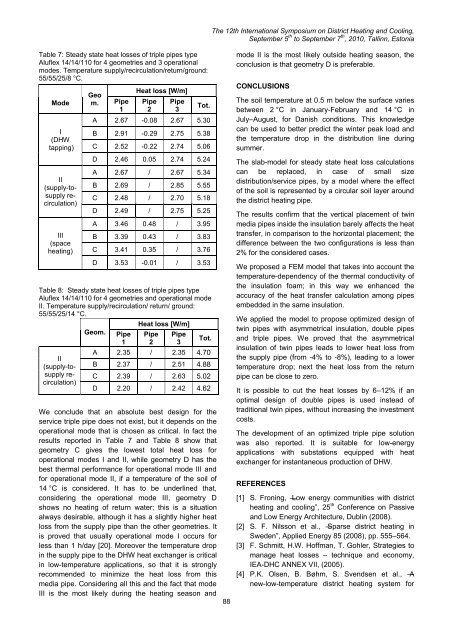
The <str<strong>on</strong>g>12th</str<strong>on</strong>g> <str<strong>on</strong>g>Internati<strong>on</strong>al</str<strong>on</strong>g> <str<strong>on</strong>g>Symposium</str<strong>on</strong>g> <strong>on</strong> <strong>District</strong> <strong>Heating</strong> <strong>and</strong> <strong>Cooling</strong>,September 5 th to September 7 th , 2010, Tallinn, Est<strong>on</strong>iaheating load periods; hence by-pass at the criticalc<strong>on</strong>sumers are not necessary <strong>and</strong> the exergy loss dueto the mixing of warm water into the return line isavoided. Furthermore the water flow in the return linehas the same directi<strong>on</strong> as in the supply line (clockwisein the example), so that the smallest size for the returnpipes are expected in corresp<strong>on</strong>dence to the biggestsize for the supply size, <strong>and</strong> vice versa. This results inlower local pressure differences between supply <strong>and</strong>return lines <strong>and</strong> savings in operati<strong>on</strong>al costs, thanks tolower heat losses. This is shown in Table 4 <strong>and</strong> Table5, by means of two examples: the first <strong>on</strong>e refers to asmall to medium-size distributi<strong>on</strong> network, the sec<strong>on</strong>d<strong>on</strong>e to a bigger <strong>on</strong>e, being capable to supply four timesmore energy than the previous <strong>on</strong>e.Triple branch pipesThe development of an optimized triple pipe soluti<strong>on</strong> forlow-energy applicati<strong>on</strong>s is reported to show thepotentiality of utilizing detailed models for steady-stateheat loss calculati<strong>on</strong>. In this survey focus was given <strong>on</strong>the choice of media pipes diameters as small aspossible. The triple pipe geometry is based <strong>on</strong>modificati<strong>on</strong>s of the 14-14/110 (outer diameters in [mm]of respectively supply pipe, return pipe, casing) twinpipe design which has been reported in [18]. Fourgeometrical variati<strong>on</strong>s have been c<strong>on</strong>sidered (seeFigure 8) <strong>and</strong> the Cartesian coordinates describing theplacement of media pipes inside the casing are listed inTable 6.Table 4: Comparis<strong>on</strong> between a distributi<strong>on</strong> networkbased <strong>on</strong> twin pipe (DN40-40 <strong>and</strong> DN80-80) with adistributi<strong>on</strong> network based <strong>on</strong> double pipe (DN40-80 <strong>and</strong>DN80-40). Supply/return/ground temperature: 55/25/8 °C.Size(DN)Heat loss [W/m]Sup. Ret. Tot.Total(system) [%]40-40 -6.24 0.04 -6.20 Twin:80-80 -7.66 0.07 -7.59 -13.7940-80 -5.55 0.05 -5.5880-40 -7.41 0.05 -7.36Double:-12.94Table 5: Comparis<strong>on</strong> between a distributi<strong>on</strong> networkbased <strong>on</strong> twin pipe (DN100-100 <strong>and</strong> DN200-200) with adistributi<strong>on</strong> network based <strong>on</strong> double pipe (DN100-200<strong>and</strong> DN200-100). Supply/return/ground: 55/25/8 °C.Size(DN)Heat loss [W/m]Sup. Ret. Tot.100-100 -7.83 -0.55 -8.39200-200 -8.92 0.24 -8.68Total(system)Twin:-17.06100-200 -6.4 0.08 -6.36 Double:200-100 -8.07 -0.03 -8.69 -15.056.1[%]11.8We c<strong>on</strong>sidered an optimal placement of the mediapipes in case of double pipes, thus asymmetricalinsulati<strong>on</strong> is applied. The total amount of insulati<strong>on</strong> isused both in the twin pipe-based distributi<strong>on</strong> network<strong>and</strong> in the double pipe-based <strong>on</strong>e, so that theinvestment costs are equal in both cases. Results showthat the heat loss can be reduced by 6% by means ofdouble pipes instead of twin pipes for the low tomedium-size distributi<strong>on</strong> network. Even higher energysavings (around 12%) are possible in the case of thelarge-size distributi<strong>on</strong> network.Figure 8: four different geometries for a triple service pipetype Aluflex 14-14/110.Table 6: placement of media pipes inside the casing forfour triple pipe geometries, type Aluflex 14-14-20/110.Variati<strong>on</strong>Pipe 1(Sup.)Coordinates (x, y) [mm]Pipe 2(Ret.)Pipe 3(Sup. orre-circ.)A (14;-14) (0;20.5) (-14;-14)B (10;-14) (0;20.5) (-21;-7)C (3;-14) (0;20.5) (-21;-7)D (0; 0) (0;25) (0;-28)The results of FEM simulati<strong>on</strong>s are listed in Table 7 forthe four geometries (A, B, C, D) <strong>and</strong> the threeoperati<strong>on</strong>al modes (I, II, II), previously described. Sincemode II occurs in case of no dem<strong>and</strong> of space heating<strong>and</strong> then outside of the heating seas<strong>on</strong>, simulati<strong>on</strong>swere additi<strong>on</strong>ally performed with a more realistictemperature of the ground during that period(14 °C),c<strong>on</strong>sidering Danish weather. This gives also aninsight in the effect of ground temperature throughoutthe year.87
The <str<strong>on</strong>g>12th</str<strong>on</strong>g> <str<strong>on</strong>g>Internati<strong>on</strong>al</str<strong>on</strong>g> <str<strong>on</strong>g>Symposium</str<strong>on</strong>g> <strong>on</strong> <strong>District</strong> <strong>Heating</strong> <strong>and</strong> <strong>Cooling</strong>,September 5 th to September 7 th , 2010, Tallinn, Est<strong>on</strong>iaTable 7: Steady state heat losses of triple pipes typeAluflex 14/14/110 for 4 geometries <strong>and</strong> 3 operati<strong>on</strong>almodes. Temperature supply/recirculati<strong>on</strong>/return/ground:55/55/25/8 °C.ModeI(DHWtapping)II(supply-tosupplyrecirculati<strong>on</strong>)III(spaceheating)Table 8: Steady state heat losses of triple pipes typeAluflex 14/14/110 for 4 geometries <strong>and</strong> operati<strong>on</strong>al modeII. Temperature supply/recirculati<strong>on</strong>/ return/ ground:55/55/25/14 °C.II(supply-tosupplyrecirculati<strong>on</strong>)Geom.Geom.Pipe1Pipe1Heat loss [W/m]Pipe2Heat loss [W/m]Pipe2Pipe3Pipe3Tot.A 2.67 -0.08 2.67 5.30B 2.91 -0.29 2.75 5.38C 2.52 -0.22 2.74 5.06D 2.46 0.05 2.74 5.24A 2.67 / 2.67 5.34B 2.69 / 2.85 5.55C 2.48 / 2.70 5.18D 2.49 / 2.75 5.25A 3.46 0.48 / 3.95B 3.39 0.43 / 3.83C 3.41 0.35 / 3.76D 3.53 -0.01 / 3.53Tot.A 2.35 / 2.35 4.70B 2.37 / 2.51 4.88C 2.39 / 2.63 5.02D 2.20 / 2.42 4.62We c<strong>on</strong>clude that an absolute best design for theservice triple pipe does not exist, but it depends <strong>on</strong> theoperati<strong>on</strong>al mode that is chosen as critical. In fact theresults reported in Table 7 <strong>and</strong> Table 8 show thatgeometry C gives the lowest total heat loss foroperati<strong>on</strong>al modes I <strong>and</strong> II, while geometry D has thebest thermal performance for operati<strong>on</strong>al mode III <strong>and</strong>for operati<strong>on</strong>al mode II, if a temperature of the soil of14 °C is c<strong>on</strong>sidered. It has to be underlined that,c<strong>on</strong>sidering the operati<strong>on</strong>al mode III, geometry Dshows no heating of return water; this is a situati<strong>on</strong>always desirable, although it has a slightly higher heatloss from the supply pipe than the other geometries. Itis proved that usually operati<strong>on</strong>al mode I occurs forless than 1 h/day [20]. Moreover the temperature dropin the supply pipe to the DHW heat exchanger is criticalin low-temperature applicati<strong>on</strong>s, so that it is str<strong>on</strong>glyrecommended to minimize the heat loss from thismedia pipe. C<strong>on</strong>sidering all this <strong>and</strong> the fact that modeIII is the most likely during the heating seas<strong>on</strong> <strong>and</strong>88mode II is the most likely outside heating seas<strong>on</strong>, thec<strong>on</strong>clusi<strong>on</strong> is that geometry D is preferable.CONCLUSIONSThe soil temperature at 0.5 m below the surface variesbetween 2 °C in January-February <strong>and</strong> 14 °C inJuly–August, for Danish c<strong>on</strong>diti<strong>on</strong>s. This knowledgecan be used to better predict the winter peak load <strong>and</strong>the temperature drop in the distributi<strong>on</strong> line duringsummer.The slab-model for steady state heat loss calculati<strong>on</strong>scan be replaced, in case of small sizedistributi<strong>on</strong>/service pipes, by a model where the effectof the soil is represented by a circular soil layer aroundthe district heating pipe.The results c<strong>on</strong>firm that the vertical placement of twinmedia pipes inside the insulati<strong>on</strong> barely affects the heattransfer, in comparis<strong>on</strong> to the horiz<strong>on</strong>tal placement; thedifference between the two c<strong>on</strong>figurati<strong>on</strong>s is less than2% for the c<strong>on</strong>sidered cases.We proposed a FEM model that takes into account thetemperature-dependency of the thermal c<strong>on</strong>ductivity ofthe insulati<strong>on</strong> foam; in this way we enhanced theaccuracy of the heat transfer calculati<strong>on</strong> am<strong>on</strong>g pipesembedded in the same insulati<strong>on</strong>.We applied the model to propose optimized design oftwin pipes with asymmetrical insulati<strong>on</strong>, double pipes<strong>and</strong> triple pipes. We proved that the asymmetricalinsulati<strong>on</strong> of twin pipes leads to lower heat loss fromthe supply pipe (from -4% to -8%), leading to a lowertemperature drop; next the heat loss from the returnpipe can be close to zero.It is possible to cut the heat losses by 6–12% if anoptimal design of double pipes is used instead oftraditi<strong>on</strong>al twin pipes, without increasing the investmentcosts.The development of an optimized triple pipe soluti<strong>on</strong>was also reported. It is suitable for low-energyapplicati<strong>on</strong>s with substati<strong>on</strong>s equipped with heatexchanger for instantaneous producti<strong>on</strong> of DHW.REFERENCES[1] S. Fr<strong>on</strong>ing, ―Low energy communities with districtheating <strong>and</strong> cooling‖, 25 th C<strong>on</strong>ference <strong>on</strong> Passive<strong>and</strong> Low Energy Architecture, Dublin (2008).[2] S. F. Nilss<strong>on</strong> et al., ―Sparse district heating inSweden‖, Applied Energy 85 (2008), pp. 555–564.[3] F. Schmitt, H.W. Hoffman, T. Gohler, Strategies tomanage heat losses – technique <strong>and</strong> ec<strong>on</strong>omy,IEA-DHC ANNEX VII, (2005).[4] P.K. Olsen, B. Bøhm, S. Svendsen et al., ―Anew-low-temperature district heating system for
- Page 1:
12th Inter
- Page 5 and 6:
The 12th I
- Page 7 and 8:
The 12th I
- Page 10 and 11:
The 12th I
- Page 12 and 13:
The 12th I
- Page 14 and 15:
For the case of parallel buried pip
- Page 16 and 17:
The 12th I
- Page 18 and 19:
The 12th I
- Page 20 and 21:
The 12th I
- Page 22 and 23:
The 12th I
- Page 24 and 25:
The 12th I
- Page 26 and 27:
The 12th I
- Page 28 and 29:
The 12th I
- Page 30 and 31:
The 12th I
- Page 32 and 33:
The 12th I
- Page 34 and 35:
The 12th I
- Page 36 and 37:
The 12th I
- Page 38 and 39: The 12th I
- Page 40 and 41: The 12th I
- Page 42 and 43: The 12th I
- Page 44 and 45: The 12th I
- Page 46 and 47: The 12th I
- Page 48 and 49: The 12th I
- Page 50 and 51: The 12th I
- Page 52 and 53: The 12th I
- Page 54 and 55: The 12th I
- Page 56 and 57: The 12th I
- Page 58 and 59: The 12th I
- Page 60 and 61: The 12th I
- Page 62 and 63: The 12th I
- Page 64 and 65: The 12th I
- Page 66 and 67: The 12th I
- Page 68 and 69: The 12th I
- Page 70 and 71: The 12th I
- Page 72 and 73: The 12th I
- Page 74 and 75: The 12th I
- Page 76 and 77: The 12th I
- Page 78 and 79: The 12th I
- Page 80 and 81: The 12th I
- Page 82 and 83: The 12th I
- Page 84 and 85: The 12th I
- Page 86 and 87: The 12th I
- Page 90 and 91: The 12th I
- Page 92 and 93: The 12th I
- Page 94 and 95: The 12th I
- Page 96 and 97: The 12th I
- Page 98 and 99: the street the more shallow the sha
- Page 100 and 101: The 12th I
- Page 102 and 103: The 12th I
- Page 104 and 105: The 12th I
- Page 106 and 107: The 12th I
- Page 108 and 109: The 12th I
- Page 110 and 111: P-1P-4P-9P-7E-5P-14P-8The 1
- Page 112 and 113: The 12th I
- Page 114 and 115: The 12th I
- Page 116 and 117: The 12th I
- Page 118 and 119: The 12th I
- Page 120 and 121: The 12th I
- Page 122 and 123: The 12th I
- Page 124 and 125: The 12th I
- Page 126 and 127: The 12th I
- Page 128 and 129: The 12th I
- Page 130 and 131: The 12th I
- Page 132 and 133: The 12th I
- Page 134 and 135: The 12th I
- Page 136 and 137: The 12th I
- Page 138 and 139:
to heating costs of 14,5 ct/kWh. Th
- Page 140 and 141:
The 12th I
- Page 142 and 143:
The 12th I
- Page 144 and 145:
The 12th I
- Page 146 and 147:
The 12th I
- Page 148 and 149:
academic access is facilitated as t
- Page 150 and 151:
The 12th I
- Page 152 and 153:
The 12th I
- Page 154 and 155:
The 12th I
- Page 156 and 157:
The 12th I
- Page 158 and 159:
The 12th I
- Page 160 and 161:
The 12th I
- Page 162 and 163:
1. CHP system operation in A2. Ther
- Page 164 and 165:
The 12th I
- Page 166 and 167:
is covered by operating HOB. In oth
- Page 168 and 169:
The 12th I
- Page 170 and 171:
The 12th I
- Page 172 and 173:
The 12th I
- Page 174 and 175:
The 12th I
- Page 176 and 177:
The 12th I
- Page 178 and 179:
The 12th I
- Page 180 and 181:
The 12th I
- Page 182 and 183:
The 12th I
- Page 184 and 185:
The 12th I
- Page 186 and 187:
The 12th I
- Page 188 and 189:
The 12th I
- Page 190 and 191:
The 12th I
- Page 192 and 193:
The 12th I
- Page 194 and 195:
The 12th I
- Page 196 and 197:
produce heat and electricity. Fluct
- Page 198 and 199:
The 12th I
- Page 200 and 201:
The 12th I
- Page 202 and 203:
The 12th I
- Page 204 and 205:
The 12th I
- Page 206 and 207:
The 12th I
- Page 208 and 209:
The 12th I
- Page 210 and 211:
To assure that the temperatures mea
- Page 212 and 213:
The 12th I
- Page 214 and 215:
The 12th I
- Page 216 and 217:
The 12th I
- Page 218 and 219:
The 12th I
- Page 220 and 221:
production and provide for marginal
- Page 222 and 223:
The 12th I
- Page 224 and 225:
The 12th I
- Page 226 and 227:
The 12th I
- Page 228 and 229:
The 12th I
- Page 230 and 231:
The 12th I
- Page 232 and 233:
The 12th I
- Page 234 and 235:
The 12th I
- Page 236 and 237:
The 12th I
- Page 238 and 239:
The 12th I
- Page 240 and 241:
The 12th I
- Page 242 and 243:
In addition, it can also be observe
- Page 244 and 245:
The 12th I
- Page 246 and 247:
owner is normally only interested i
- Page 248 and 249:
The 12th I
- Page 250 and 251:
The 12th I
- Page 252 and 253:
The 12th I
- Page 254 and 255:
The 12th I
- Page 256 and 257:
The 12th I
- Page 258 and 259:
The 12th I
- Page 260 and 261:
The 12th I
- Page 262 and 263:
The 12th I
- Page 264 and 265:
The 12th I
- Page 266 and 267:
The 12th I
- Page 268 and 269:
The 12th I
- Page 270 and 271:
The 12th I
- Page 272 and 273:
The 12th I
- Page 274 and 275:
The 12th I
- Page 276 and 277:
The 12th I
- Page 278 and 279:
The 12th I
- Page 280 and 281:
The 12th I
- Page 282 and 283:
The 12th I
- Page 284 and 285:
The 12th I
- Page 286 and 287:
The 12th I
- Page 288 and 289:
The 12th I
- Page 290 and 291:
Stockholm district heating system a
- Page 292 and 293:
The 12th I
- Page 294 and 295:
The 12th I
- Page 296 and 297:
The 12th I
- Page 298 and 299:
The 12th I
- Page 300 and 301:
The 12th I
- Page 302 and 303:
The 12th I
- Page 304 and 305:
The 12th I
- Page 306 and 307:
The 12th I
- Page 308 and 309:
The 12th I
- Page 310 and 311:
The 12th I
- Page 312 and 313:
The 12th I
- Page 314 and 315:
The values presented do of course l
- Page 316 and 317:
The 12th I
- Page 318 and 319:
The 12th I
- Page 320 and 321:
The 12th I
- Page 322 and 323:
The 12th I
- Page 324 and 325:
The 12th I
- Page 326:
The 12th I