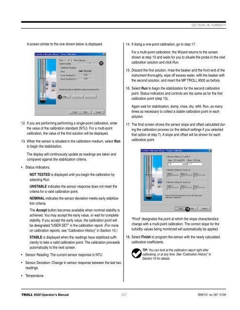
Section 18: TurbidityA screen similar to the one shown below is displayed.1312. If you are performing performing a single-point calibration, enterthe value of the calibration standard (NTU). For a multi-pointcalibration, the value of the first solution will be displayed.13. When the sensor is situated in the calibration medium, select Runto begin the stabilization.1214. If doing a one-point calibration, go to step 17.For a multi-point calibration, the Wizard returns to the screenshown at step 13 and waits for you to situate the probe in the nextcalibration solution and click Run.15. Discard the first solution, rinse the beaker and the front end of theinstrument thoroughly, wipe off excess water, refill the beaker withthe second solution, and insert the MP <strong>TROLL</strong> <strong>9500</strong> as before.16. Select Run to begin the stabilization for the second calibrationpoint. Status indicators and controls are the same as for the firstcalibration point (step 13).Again wait for stabilization, dump, rinse, dry, refill, Run, as manytimes as necessary to collect a stable calibration point in eachsolution.17. The final screen shows the sensor slope and offset calculated duringthe calibration process (or the default settings if you selectedthat option at step 7). A slope and offset will be shown for eachcalibration point.The display will continuously update as readings are taken andcompared against the stabilization criteria.• Status indicators:NOT TESTED is displayed until you begin the calibration byselecting Run.UNSTABLE indicates the sensor response does not meet thecriteria for a valid calibration point.NOMINAL indicates the sensor deviation meets early stabilizationcriteria.The Accept button becomes available when nominal stability isachieved. You may accept the early value, or wait for completestability. If you accept the early value, the calibration point willbe designated “USER SET” in the calibration report. (For moreon calibration reports, see “Calibration History” in Section 10.)STABLE is displayed when the readings have stabilized sufficientlyto take a valid calibration point. The calibration proceedsautomatically to the next screen.• Sensor Reading: The current sensor response in NTU• Sensor Deviation: Change in sensor response between the last tworeadings.“Pivot” designates the point at which the slope characteristicschange with a multi-point calibration. The correct slope for theturbidity values being monitored will automatically be applied.18. Select Finish to program the sensor with the newly calculatedcalibration coefficients.TIP: You can look at the calibration report right aftercalibrating, or at any time. See “Calibration History” inSection 10 for details.18• Temperature<strong>TROLL</strong> <strong>9500</strong> Operator’s <strong>Manual</strong> 1270095110 rev. 007 01/09
Section 18: TurbidityResetting Default CoefficientsThe sensor’s calibration may be reset back to factory defaults at anytime. As long as there is no contamination on the optical windows, thiswill restore the factory accuracy (± 5% or 2 NTU).1. Establish a connection to the instrument in Win-Situ 4 or Pocket-Situ 4.2. Select Turbidity in the Parameters list and click Calibrate.3. In the first screen, select Use Default Coefficients, then Next.4. In the final screen, click Finish to restore the sensor’s factorycalibration coefficients.Sensor Slope and OffsetThe offset is factory-set at 0 NTU. The zero offset may be recalculatedfor any appropriate value by performing a single-point calibrationusing a calibration standard of the desired NTU value. The sensorresponse is very linear up to 200 NTU.Units and Calculated MeasurementsTwo units are available for readings from the turbidity channel:• NTUs—Nephelometric Turbidity Units. Select NTU when the sensorhas been calibrated with polymer suspensions.• FNUs—Formazin Turbidity Units. Select FNU when the sensor hasbeen calibrated with Formazin.Usage Recommendations and CautionsThe operational pressure rating of the turbidit y sensor is150 psi. Do not submerge it deeper than 346 ft (105 m).Avoid use of the stirrer accessory (recommended for monitoring dissolvedoxygen in stagnant water) when measuring turbidity.When used without a wiper, dirty sensor optics can be compensatedfor to some extent by changing the offset.Optical absorbancy (“color”) will lessen the turbidity signal.Turbidity readings are temperature-commpensated.The optics need 5 seconds warm-up time to take the first readinglater. Subsequent readings can be returned instantaneously.Common InterferencesLight scattering depends upon the size, shape, refractive index, andother characteristics of the particles and the wavelength of the light.Optically black particles, such as those of activated carbon, mayabsorb light and effectively decrease turbidity measurements.Nephelometers are relatively unaffected by small changes in designparameters and therefore are specified as the standard instrument formeasurement of low turbidities. Nonstandard turbidimeters, such asforward-scattering devices, are more sensitive than nephelometers tothe presence of larger particles and are useful for process monitoring.Reported turbidities are heavily dependent on the particulate mattercontained in the suspensions that are used to prepare instrumentcalibration curves.Due to current technological limitations, field turbidity measurementis “a snapshot of averages,” Field measurements can be an excellentindicator of in-situ turbidity; final determination for reporting purposesshould be conducted in a laboratory.Profiling TurbidityThe turbidity sensor’s 5-second warmup will result in a slight delay beforethe first Profiler reading for all parameters. Subsequent readingscan be taken within the Profiler’s 2-second cycling.If a turbidity wiper accessory is installed, it performs an initial wipe ofthe sensor optics—this takes about 15 seconds—then displays thefirst turbidity reading. If the profiling rate is longer than 15 seconds,this 15 second wipe will happen before each reading. To avoid thisdelay, set the profiling rate to less than 15 seconds. See Customizingthe Profiler in Section 5 for details.Logging Turbidity DataThe wiper is activated automatically before turbidity readings duringtests, so long as the readings are 15 seconds or more apart. Toprolong battery life when running a wiper, we recommend the useof external power or two internal lithium D-cells installed in the MP<strong>TROLL</strong> <strong>9500</strong>.Sensor CareInspection/Maintenance/CleaningThe optical windows of the sensor are made of scratch-resistantsapphire. The optical components are not user-serviceable. Seriousmechanical and temperature shock are about the only things that candamage the LED. If you feel the instrument has suffered such damage,contact In-Situ Technical Support.However, the windows may need frequent cleaning, especially if usedin a biologically active environment. A wiper accessory can help toprevent the accumulation of foreign material.<strong>TROLL</strong> <strong>9500</strong> Operator’s <strong>Manual</strong> 1280095110 rev. 007 01/09