TROLL 9500 Operator's Manual - Geotech Environmental Equipment
TROLL 9500 Operator's Manual - Geotech Environmental Equipment
TROLL 9500 Operator's Manual - Geotech Environmental Equipment

You also want an ePaper? Increase the reach of your titles
YUMPU automatically turns print PDFs into web optimized ePapers that Google loves.
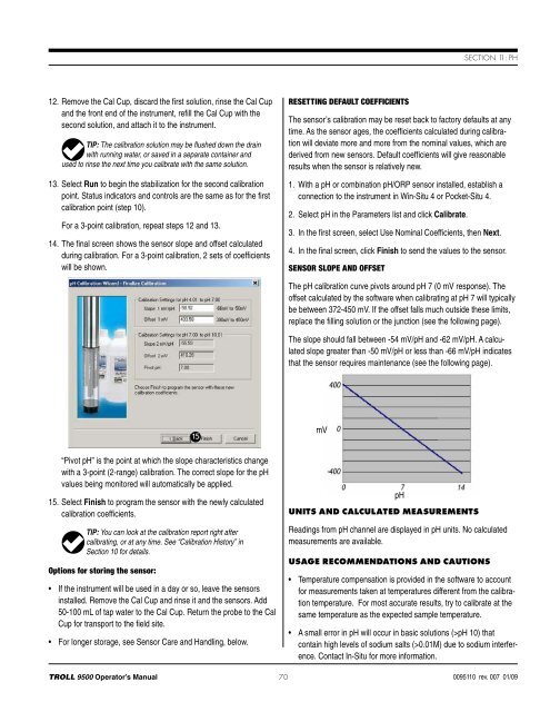
Section 11: pH12. Remove the Cal Cup, discard the first solution, rinse the Cal Cupand the front end of the instrument, refill the Cal Cup with thesecond solution, and attach it to the instrument.TIP: The calibration solution may be flushed down the drainwith running water, or saved in a separate container andused to rinse the next time you calibrate with the same solution.13. Select Run to begin the stabilization for the second calibrationpoint. Status indicators and controls are the same as for the firstcalibration point (step 10).For a 3-point calibration, repeat steps 12 and 13.14. The final screen shows the sensor slope and offset calculatedduring calibration. For a 3-point calibration, 2 sets of coefficientswill be shown.Resetting Default CoefficientsThe sensor’s calibration may be reset back to factory defaults at anytime. As the sensor ages, the coefficients calculated during calibrationwill deviate more and more from the nominal values, which arederived from new sensors. Default coefficients will give reasonableresults when the sensor is relatively new.1. With a pH or combination pH/ORP sensor installed, establish aconnection to the instrument in Win-Situ 4 or Pocket-Situ 4.2. Select pH in the Parameters list and click Calibrate.3. In the first screen, select Use Nominal Coefficients, then Next.4. In the final screen, click Finish to send the values to the sensor.Sensor Slope and OffsetThe pH calibration curve pivots around pH 7 (0 mV response). Theoffset calculated by the software when calibrating at pH 7 will typicallybe between 372-450 mV. If the offset falls much outside these limits,replace the filling solution or the junction (see the following page).The slope should fall between -54 mV/pH and -62 mV/pH. A calculatedslope greater than -50 mV/pH or less than -66 mV/pH indicatesthat the sensor requires maintenance (see the following page).15mV“Pivot pH” is the point at which the slope characteristics changewith a 3-point (2-range) calibration. The correct slope for the pHvalues being monitored will automatically be applied.15. Select Finish to program the sensor with the newly calculatedcalibration coefficients.TIP: You can look at the calibration report right aftercalibrating, or at any time. See “Calibration History” inSection 10 for details.Options for storing the sensor:• If the instrument will be used in a day or so, leave the sensorsinstalled. Remove the Cal Cup and rinse it and the sensors. Add50-100 mL of tap water to the Cal Cup. Return the probe to the CalCup for transport to the field site.• For longer storage, see Sensor Care and Handling, below.pHUnits and Calculated MeasurementsReadings from pH channel are displayed in pH units. No calculatedmeasurements are available.Usage Recommendations and Cautions• Temperature compensation is provided in the software to accountfor measurements taken at temperatures different from the calibrationtemperature. For most accurate results, try to calibrate at thesame temperature as the expected sample temperature.• A small error in pH will occur in basic solutions (>pH 10) thatcontain high levels of sodium salts (>0.01M) due to sodium interference.Contact In-Situ for more information.<strong>TROLL</strong> <strong>9500</strong> Operator’s <strong>Manual</strong> 700095110 rev. 007 01/09