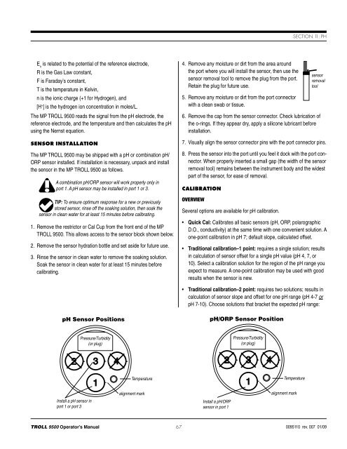
Section 11: pHE ois related to the potential of the reference electrode,R is the Gas Law constant,F is Faraday’s constant,T is the temperature in Kelvin,n is the ionic charge (+1 for Hydrogen), and[H + ] is the hydrogen ion concentration in moles/L.The MP <strong>TROLL</strong> <strong>9500</strong> reads the signal from the pH electrode, thereference electrode, and the temperature and then calculates the pHusing the Nernst equation.Sensor InstallationThe MP <strong>TROLL</strong> <strong>9500</strong> may be shipped with a pH or combination pH/ORP sensor installed. If installation is necessary, unpack and installthe sensor in the MP <strong>TROLL</strong> <strong>9500</strong> as follows.A combination pH/ORP sensor will work properly only inport 1. A pH sensor may be installed in port 1 or 3.TIP: To ensure optimum response for a new or previouslystored sensor, rinse off the soaking solution, then soak thesensor in clean water for at least 15 minutes before calibrating.1. Remove the restrictor or Cal Cup from the front end of the MP<strong>TROLL</strong> <strong>9500</strong>. This allows access to the sensor block shown below.2. Remove the sensor hydration bottle and set aside for future use.3. Rinse the sensor in clean water to remove the soaking solution.Soak the sensor in clean water for at least 15 minutes beforecalibrating.4. Remove any moisture or dirt from the area aroundthe port where you will install the sensor, then use thesensor removal tool to remove the plug from the port.Retain the plug for future use.5. Remove any moisture or dirt from the port connectorwith a clean swab or tissue.sensorremovaltool6. Remove the cap from the sensor connector. Check lubrication ofthe o-rings. If they appear dry, apply a silicone lubricant beforeinstallation.7. Visually align the sensor connector pins with the port connector pins.8. Press the sensor into the port until you feel it dock with the port connector.When properly inserted a small gap (the width of the sensorremoval tool) remains between the instrument body and the widestpart of the sensor, for ease of removal.CalibrationOverviewSeveral options are available for pH calibration.• Quick Cal: Calibrates all basic sensors (pH, ORP, polarographicD.O., conductivity) at the same time with one convenient solution. Aone-point calibration in pH 7; default slope, calculated offset.• Traditional calibration–1 point: requires a single solution; resultsin calculation of sensor offset for a single pH value (pH 4, 7, or10). Select a calibration solution for the region of the pH range youexpect to measure. A one-point calibration may be used with goodresults when the sensor is new.• Traditional calibration–2 point: requires two solutions; results incalculation of sensor slope and offset for one pH range (pH 4-7 orpH 7-10). Choose solutions that bracket the expected pH range:pH Sensor PositionspH/ORP Sensor PositionPressure/Turbidity(or plug)Pressure/Turbidity(or plug)TemperatureTemperatureInstall a pH sensor inport 1 or port 3alignment markInstall a pH/ORPsensor in port 1alignment mark<strong>TROLL</strong> <strong>9500</strong> Operator’s <strong>Manual</strong> 670095110 rev. 007 01/09
Section 11: pH• 4.0 and 7.0 pH buffer solutions for neutral to acidic conditions• 7.0 and 10.0 pH buffer solutions for neutral to basic conditions• Traditional calibration–3 point: requires three solutions; results incalculation of slope and offset for 2 ranges (pH 4-7 and pH 7-10).The correct slope for the pH values being monitored will automaticallybe applied. A 3-point calibration is useful when the pH rangeof the environmental fluid is completely unknown.• Resets the sensor’s factory defaults. No solutions are required.Nominal vs. StableTo shorten the calibration time, you have the option to accept thecalibration when “Nominal” stability conditions are achieved. If theearly value is accepted, the calibration point will be designated “USERSET” in the calibration report. If the calibration report indicates thatcalibration was performed through to stability then the instrument willoperate as intended by In-Situ’s quality standards.Calibration SolutionsCalibration solutions certified to N.I.S.T. standards are supplied in theIn-Situ pH Calibration Kit: pH 4, pH 7, pH 10 buffer, and deionizedwater. Catalog No. 0032080. Solutions are also available separately.TIP: Most solutions are usable beyond their stated expirationdate, depending on storage conditions; however, the resultscannot be guaranteed.Primary standard buffer salts are available from the National Bureauof Standards, and may be used in situations where extreme accuracyis required. Commercially available pH buffers may be used.Recommended Calibration FrequencyCalibration frequency will depend on the nature of the sample and thedegree of accuracy required. In clean water samples, the pH sensorshould retain its accuracy for 2-6 weeks before requiring recalibration.Recalibrate the sensor—• after replacing the reference junction and/or the filling solution,• during routine, scheduled maintenance,Recommended Calibration Order for pH and ORP• every 2-6 weeks in the absence of other indications.pH Quick CalThe procedure to Quick Cal the pH sensor (a 1-point calibration at pH7), along with other sensors in the Basic Sensor Set, may be found inSection 3, Getting Started.To perform a more accurate traditional calibration, follow the procedurebelow.TIP: The pH calibration procedure is the same for pHsensors and pH/ORP sensors.Traditional pH Calibration Procedure1. With a pH or pH/ORP sensor installed and plugs or sensors in theother ports, rinse the front end of the MP <strong>TROLL</strong> <strong>9500</strong> in tap water,then again in deionized water. Shake to dry.For the most accurate results, follow this with a rinse in a portion ofthe selected calibration solution.2. Insure the black PVC base is attached to the Cal Cup, and fill theCal Cup to the fill line with the selected calibrationsolution.• Begin with the lowest buffer value when performinga multi-point calibration.• With a full complement of sensors installed, usethe lower line as a guide.• With 1 or 2 removable sensors installed, fill to theupper line.3. Insert the front end of the MP <strong>TROLL</strong> <strong>9500</strong> into theopen end of the Cal Cup. Thread the Cal Cup ontothe body until seated against the o-ring, then backoff slightly to avoid overtightening.4. Connect the MP <strong>TROLL</strong> <strong>9500</strong> to a PC and establisha connection in Win-Situ 4 or Pocket-Situ 4. Win-Situ screens areillustrated here. The Pocket-Situ interface is similar, with the Navigationtree at the top of the screen and the Information pane belowit.3The pH/ORP sensor requires separate calibrations for pH and ORP.A suggested calibration scenario is as follows:A. First, Quick-Cal ORP (plus, optionally, other installed Basic sensors).For the procedure, see Section 3, Getting Started.B. Then, perform a 2- or 3-point Traditional pH calibration asdescribed here.<strong>TROLL</strong> <strong>9500</strong> Operator’s <strong>Manual</strong> 680095110 rev. 007 01/09