TROLL 9500 Operator's Manual - Geotech Environmental Equipment
TROLL 9500 Operator's Manual - Geotech Environmental Equipment
TROLL 9500 Operator's Manual - Geotech Environmental Equipment

You also want an ePaper? Increase the reach of your titles
YUMPU automatically turns print PDFs into web optimized ePapers that Google loves.
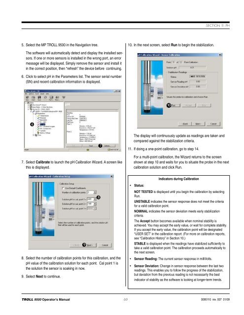
Section 11: pH5. Select the MP <strong>TROLL</strong> <strong>9500</strong> in the Navigation tree.10. In the next screen, select Run to begin the stabilization.The software will automatically detect and display the installed sensors.If one or more sensors is installed in the wrong port, an errormessage will be displayed. Simply remove the sensor and install itin the correct position, then “refresh” the device before continuing.6. Click to select pH in the Parameters list. The sensor serial number(SN) and recent calibration information is displayed.1067. Select Calibrate to launch the pH Calibration Wizard. A screen likethis is displayed.7The display will continuously update as readings are taken andcompared against the stabilization criteria.11. If doing a one-point calibration, go to step 14.For a multi-point calibration, the Wizard returns to the screenshown at step 10 and waits for you to situate the probe in the nextcalibration solution and click Run.Indicators during Calibration• Status:8. Select the number of calibration points for this calibration, and thepH value of the calibration solution for each point. Cal point 1 isthe solution the sensor is soaking in now.9. Select Next to continue.98NOT TESTED is displayed until you begin the calibration by selectingRun.UNSTABLE indicates the sensor response does not meet the criteriafor a valid calibration point.NOMINAL indicates the sensor deviation meets early stabilizationcriteria.The Accept button becomes available when nominal stability isachieved. You may accept the early value, or wait for complete stability.If you accept the early value, the calibration point will be designated“USER SET” in the calibration report. (For more on calibration reports,see “Calibration History” in Section 10.)STABLE is displayed when the readings have stabilized sufficiently totake a valid calibration point. The calibration proceeds automatically tothe next screen.• Sensor Reading: The current sensor response in milliVolts.• Sensor Deviation: Change in sensor response between the last tworeadings. This enables you to follow the progress of the stabilization,but deviation from the previous reading is not necessarily the bestindicator of stability as the software is looking at longer-term trends.<strong>TROLL</strong> <strong>9500</strong> Operator’s <strong>Manual</strong> 690095110 rev. 007 01/09