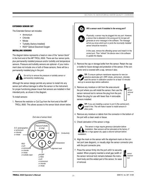
Section 10: Monitoring Water Quality: OverviewExtended Sensor SetThe Extended Sensor set includes:• Ammonium• Chloride• Nitrate• Turbidity (factory-installed)• RDO ® Optical Dissolved OxygenInstalling SensorsThe diagram below represents a head-on view of the “sensor block”in the front end of the MP <strong>TROLL</strong> <strong>9500</strong>. There are four sensor ports,plus permanently installed pressure and/or turbidity and temperaturesensors. Pressure and turbidity sensors are optional—if your instrumentdoes not include one or both of these sensors, there will be apermanently installed plug in the port.Do not try to remove the pressure or turbidity sensor orpermanently installed plug.Although the sensor design permits any sensor to install into anysensor port without damage to either the sensor or the instrument,for proper functioning please insure that sensors are installed in theirintended ports, as shown in the diagram.To install sensors:1. Remove the restrictor or Cal Cup from the front end of the MP<strong>TROLL</strong> <strong>9500</strong>. This allows access to the sensor block shown below.End view of sensor blockQ:A:Will a sensor work if installed in the wrong port?Physically, a sensor may be plugged into any port. However,a sensor that is detected in the wrong port for its type willgenerate an error message in the software. The messagewill let you know which port or ports the incorrectly installedsensor should be moved to.In this case, remove the offending sensor and install it in thecorrect port. Then “refresh” the device view in the softwareto update the display.2. Remove the cap or storage bottle from the sensor. Retain the capor bottle for future storage and protection of the sensor. If the connectorend is covered with a cap, remove it also.TIP: To ensure optimum membrane response for new ionselectiveelectrodes (pH, ORP, nitrate, ammonium, chloride),soak the sensor in calibration solution for at least 15 minutesand up to several days before calibration.3. Remove any moisture or dirt from the area aroundthe port where you will install the sensor, then use thesensor removal tool to remove the plug from the port.Retain the plug for use with fewer than 4 removablesensors installed.TIP: If you are installing a sensor in port 3 (the central port),install it first. This will make it easier to install sensors inother ports.sensorremovaltool4. Remove any moisture or debris from the connector in the bottom ofthe port with a clean swab or tissue.5. Check lubrication of the sensor o-rings.D.O. (polarographic)or ammoniumor chlorideor nitratePressure/Turbidity(or plug)ConductivityThe sensor o-rings require generous lubrication beforeinstallation. New sensors will be lubricated at the factory. Ifthe o-rings appear dry, apply a silicone lubricant beforeinstallation.RDOor pHor ammoniumor chlorideor nitrateor turbidity wiperpH/ORPor RDOor pHor ammoniumor chlorideor nitrateTemperaturealignment mark6. Align the mark on the sensor with the alignment mark on the correctport (see diagram), or visually align the sensor connector pinswith the port connector pins.7. Press the sensor firmly into the port until it is securelyseated. When properly inserted a small gap (width ofthe sensor removal tool) remains between the instrumentbody and the widest part of the sensor, for easeof removal.sensorinsertiontool<strong>TROLL</strong> <strong>9500</strong> Operator’s <strong>Manual</strong> 590095110 rev. 007 01/09
Section 10: Monitoring Water Quality: OverviewRemoving SensorsSensors may be removed for inspection, cleaning, routine maintenance,and storage. Because the smart sensors retain calibrationinformation, they may be removed and re-installed—even in anotherMP <strong>TROLL</strong> <strong>9500</strong>— as often as necessary.Remove a sensor by positioning the yoke of the sensorremoval tool at the point where the sensor enters thesensor block. Firmly pry the sensor upward until it popsout.Sensor O-RingssensorremovaltoolTwo Viton® o-rings on each sensor provide a watertight seal againstwater leakage into the instrument body. We recommend that youinspect these o-rings each time you remove or install a sensor. Checkcarefully for cracks, tears, splitting, shredding, and other damage. Ifthe o-rings are in good condition, apply silicone lubricant before installingthe sensor again. Remove excess lubricant with a tissue, andtake care to keep grease away from the area around the connector atthe bottom of the sensor. Should lubricant get into this area, it can beremoved with a clean cotton swab.If the o-rings become damaged to the extent that no longer provide aneffective seal, they should be replaced. Sensor o-rings and lubricantare available from In-Situ Inc. or your distributor.Calibration OverviewThe MP <strong>TROLL</strong> <strong>9500</strong> and its control software provide several optionsfor calibration of the water-quality sensors. Select the method thatsuits the time you have at your disposal and the degree of accuracyyou want to achieve when measuring water-quality parameters.Satisfactory results may be achieved using the Quick Cal procedure.Some sensors can even return nominal results straight out of the boxusing the factory-supplied default calibration coefficients. However,for best results we recommend a full traditional calibration procedurebefore the first field use, and periodic checks and recalibrations asnecessary thereafter.The following available options are briefly described in the next twopages:• Traditional Calibration• Quick Calibration• Out-of-Box• Factory DefaultsTraditional CalibrationA full traditional calibration, guided by software wizards, can achievethe highest level of accuracy. Some sensors require a single-pointcalibration, others present a choice of single- or multi-point, requiringmore than one calibration standard. A single-point calibrationgives good results in the range of values represented by the selectedcalibration solution. When a wide range of values are expected, amulti-point calibration is recommended.With the sensor installed in the MP <strong>TROLL</strong> 9000 and immersed incalibration solution, the sensor is powered at regular intervals andits response is monitored. The difference (deviation) between theminimum and maximum response over a predetermined time periodis tracked by the software. When the peaks of the response fall withinpredetermined limits for the time period, the sensor response isconsidered sufficiently stable to provide a valid calibration point. Thelength of time and allowable deviation are specific to each sensortype, and furthermore are specific to the determination of nominalstability or complete stability. The time period of interest is shorter fornominal stability than for complete stability, allowing for a shorteningof the calibration soak time while still returning a valid calibration point.• Available for: All water-quality parameters.• Requirements: MP <strong>TROLL</strong> <strong>9500</strong>, sensors (installed), Cal Cup,and one or more calibration solutions for each parameter to becalibrated. Suitable calibration solutions are supplied in In-Situ’sindividual calibration kits.• Where to find the method in this manual: Sections 11-19.Q:A:What is the difference between NOMINAL and STABLE?To meet the criteria for a valid calibration point, the change(deviation) in sensor response is monitored over time. Thesoftware is looking for the calibration solution temperatureand the sensor readings to settle over a specific time period.The criteria for STABLE are designed to meet the publishedspecifications. The NOMINAL criteria are designed toshorten the calibration time when an approximate calibrationis acceptable. When the deviation falls within the limits ofthe “loosened” specifications, NOMINAL is displayed in theStatus area, and the Accept button becomes available tostore the current calibration point.Accepting a NOMINAL value may save considerable time.In some cases, especially if the sensors have been soakingin the solution for several minutes prior to calibration, theaccuracy achieved by accepting a nominal value may bevery similar to that obtained by waiting for complete stability.<strong>TROLL</strong> <strong>9500</strong> Operator’s <strong>Manual</strong> 600095110 rev. 007 01/09