TROLL 9500 Operator's Manual - Geotech Environmental Equipment
TROLL 9500 Operator's Manual - Geotech Environmental Equipment
TROLL 9500 Operator's Manual - Geotech Environmental Equipment

Create successful ePaper yourself
Turn your PDF publications into a flip-book with our unique Google optimized e-Paper software.
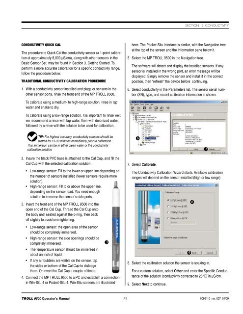
Section 12: ConductivityConductivity Quick CalThe procedure to Quick Cal the conductivity sensor (a 1-point calibrationat approximately 8,000 µS/cm), along with other sensors in theBasic Sensor Set, may be found in Section 3, Getting Started. Toperform a more accurate calibration for a specific conductivity range,follow the procedure below.Traditional Conductivity Calibration Procedure1. With a conductivity sensor installed and plugs or sensors in theother sensor ports, rinse the front end of the MP <strong>TROLL</strong> <strong>9500</strong>.here. The Pocket-Situ interface is similar, with the Navigation treeat the top of the screen and the Information pane below it.5. Select the MP <strong>TROLL</strong> <strong>9500</strong> in the Navigation tree.The software will detect and display the installed sensors. If anysensor is installed in the wrong port, an error message will bedisplayed. Simply remove the sensor and install it in the correctposition, then “refresh” the device before continuing.6. Select conductivity in the Parameters list. The sensor serial number(SN), type, and recent calibration information is shown.To calibrate using a medium- to high-range solution, rinse in tapwater and shake to dry.To calibrate using a low-range solution, it is important to rinse well;we recommend a rinse with tap water, then with deionized water,followed by a rinse with the solution to be used for calibration.TIP: For highest accuracy, conductivity sensors should bewetted for 15-30 minutes immediately prior to calibration.This immersion can be in either clean water or the conductivitycalibration solution.672. Insure the black PVC base is attached to the Cal Cup, and fill theCal Cup with the selected calibration solution.• Low-range sensor: Fill to the lower or upper line depending onthe number of sensors installed (fewer sensors require moresolution).• High-range sensor: Fill to or above the upper line,depending on the sensor load. You need enoughsolution to immerse the sensor’s side ports.3. Insert the front end of the MP <strong>TROLL</strong> <strong>9500</strong> into theopen end of the Cal Cup. Thread the Cal Cup ontothe body until seated against the o-ring, then backoff slightly to avoid overtightening.• Low-range sensor: the open area of the sensorshould be completely immersed.• High-range sensor: the side openings should becompletely immersed.3• The temperature sensor should be immersed inabout an inch of liquid.• If any air bubbles are visible on the sensor, tapthe sides or bottom of the Cal Cup to dislodgethem. Or invert the Cal Cup a couple of times.4. Connect the MP <strong>TROLL</strong> <strong>9500</strong> to a PC and establish a connectionin Win-Situ 4 or Pocket-Situ 4. Win-Situ screens are illustrated7. Select Calibrate.The Conductivity Calibration Wizard starts. Available calibrationranges will depend on the sensor installed (high or low range)8. Select the calibration solution the sensor is soaking in.For a custom solution, select Other and enter the Specific Conductanceof the solution (conductivity corrected to 25°C) in µS/cm.9. Select Next to continue.98<strong>TROLL</strong> <strong>9500</strong> Operator’s <strong>Manual</strong> 740095110 rev. 007 01/09