TROLL 9500 Operator's Manual - Geotech Environmental Equipment
TROLL 9500 Operator's Manual - Geotech Environmental Equipment
TROLL 9500 Operator's Manual - Geotech Environmental Equipment

You also want an ePaper? Increase the reach of your titles
YUMPU automatically turns print PDFs into web optimized ePapers that Google loves.
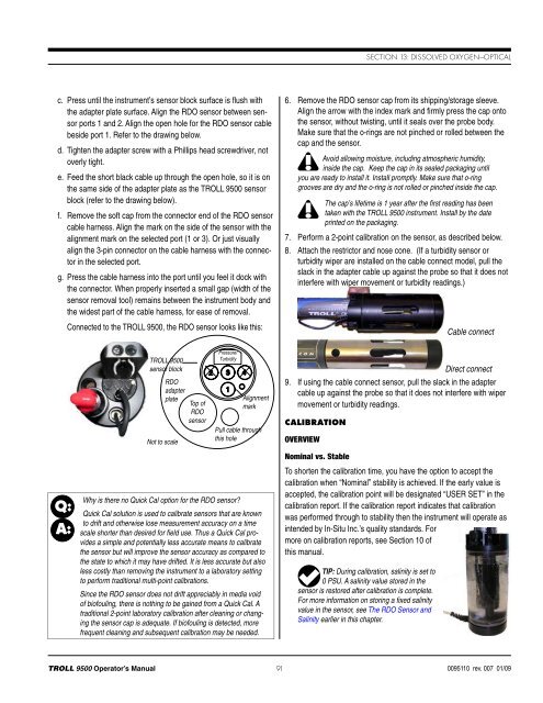
Section 13: Dissolved Oxygen—Opticalc. Press until the instrument’s sensor block surface is flush withthe adapter plate surface. Align the RDO sensor between sensorports 1 and 2. Align the open hole for the RDO sensor cablebeside port 1. Refer to the drawing below.d. Tighten the adapter screw with a Phillips head screwdriver, notoverly tight.e. Feed the short black cable up through the open hole, so it is onthe same side of the adapter plate as the <strong>TROLL</strong> <strong>9500</strong> sensorblock (refer to the drawing below).f. Remove the soft cap from the connector end of the RDO sensorcable harness. Align the mark on the side of the sensor with thealignment mark on the selected port (1 or 3). Or just visuallyalign the 3-pin connector on the cable harness with the connectorin the selected port.g. Press the cable harness into the port until you feel it dock withthe con nector. When properly inserted a small gap (width of thesensor removal tool) remains between the instrument body andthe widest part of the cable harness, for ease of removal.Connected to the <strong>TROLL</strong> <strong>9500</strong>, the RDO sensor looks like this:6. Remove the RDO sensor cap from its shipping/storage sleeve.Align the arrow with the index mark and firmly press the cap ontothe sensor, without twisting, until it seals over the probe body.Make sure that the o-rings are not pinched or rolled between thecap and the sensor.Avoid allowing moisture, including atmospheric humidity,inside the cap. Keep the cap in its sealed packaging untilyou are ready to install it. Install promptly. Make sure that o-ringgrooves are dry and the o-ring is not rolled or pinched inside the cap.The cap’s lifetime is 1 year after the first reading has beentaken with the <strong>TROLL</strong> <strong>9500</strong> instrument. Install by the dateprinted on the packaging.7. Perform a 2-point calibration on the sensor, as described below.8. Attach the restrictor and nose cone. (If a turbidity sensor orturbidity wiper are installed on the cable connect model, pull theslack in the adapter cable up against the probe so that it does notinterfere with wiper movement or turbidity readings.)Cable connectQ:A:<strong>TROLL</strong> <strong>9500</strong>sensor blockRDOadapterplateNot to scaleTop ofRDOsensorPressure/TurbidityAlignmentmarkPull cable throughthis holeWhy is there no Quick Cal option for the RDO sensor?Quick Cal solution is used to calibrate sensors that are knownto drift and otherwise lose measurement accuracy on a timescale shorter than desired for field use. Thus a Quick Cal providesa simple and potentially less accurate means to calibratethe sensor but will improve the sensor accuracy as compared tothe state to which it may have drifted. It is less accurate but alsoless costly than removing the instrument to a laboratory settingto perform traditional multi-point calibrations.Since the RDO sensor does not drift appreciably in media voidof biofouling, there is nothing to be gained from a Quick Cal. Atraditional 2-point laboratory calibration after cleaning or changingthe sensor cap is adequate. If biofouling is detected, morefrequent cleaning and subsequent calibration may be needed.Direct connect9. If using the cable connect sensor, pull the slack in the adaptercable up against the probe so that it does not interfere with wipermovement or turbidity readings.CalibrationOverviewNominal vs. StableTo shorten the calibration time, you have the option to accept thecalibration when “Nominal” stability is achieved. If the early value isaccepted, the calibration point will be designated “USER SET” in thecalibration report. If the calibration report indicates that calibrationwas performed through to stability then the instrument will operate asintended by In-Situ Inc.’s quality standards. Formore on calibration reports, see Section 10 ofthis manual.TIP: During calibration, salinity is set to0 PSU. A salinity value stored in thesensor is restored after calibration is complete.For more information on storing a fixed salinityvalue in the sensor, see The RDO Sensor andSalinity earlier in this chapter.<strong>TROLL</strong> <strong>9500</strong> Operator’s <strong>Manual</strong> 910095110 rev. 007 01/09