- Seite 1 und 2:
Tank + Chemie-Schläuche1Petrol + C
- Seite 3 und 4:
GRUPPE GE-WICHT1 WeightApprox.SCHLA
- Seite 5 und 6:
TECHNISCHE ÄNDERUNGEN VORBEHALTEN
- Seite 7 und 8:
'ltX' -leicht-tankwagenschlauchfür
- Seite 9 und 10:
GRUPPE GE-WICHT1 WeightApprox.SCHLA
- Seite 11 und 12:
TECHNISCHE ÄNDERUNGEN VORBEHALTEN
- Seite 13 und 14:
GRUPPE GE-WICHT1 WeightApprox.SCHLA
- Seite 15 und 16:
GRUPPE GE-WICHT1 WeightApprox.SCHLA
- Seite 17 und 18:
GRUPPE GE-WICHT1 WeightApprox.SCHLA
- Seite 19 und 20:
GRUPPE GE-WICHT1 WeightApprox.SCHLA
- Seite 21 und 22:
GRUPPE GE-WICHT1 WeightApprox.SCHLA
- Seite 23 und 24:
GRUPPE1SectionGe- SCHLAUCH- BESTELL
- Seite 25 und 26:
ELAPHARM ®Schlauchleitungen für d
- Seite 27 und 28:
Gruppe Gewicht1 WeightApprox.Schlau
- Seite 29 und 30:
GRUPPE GE-WICHT1 WeightApprox.SCHLA
- Seite 31 und 32:
GRUPPE1SectionGE- SCHLAUCH- BESTELL
- Seite 33 und 34:
' FLUORFLEX 2 'PTFE / EPDM Universa
- Seite 35 und 36:
Gruppe GewichtWeight1Approx.Schlauc
- Seite 37 und 38:
GRUPPE GE-WICHT1 WeightApprox.SCHLA
- Seite 39 und 40:
GRUPPE GE-WICHT1 WeightApprox.SCHLA
- Seite 41 und 42:
GRUPPE1 WeightApprox.GE- SCHLAUCH-W
- Seite 43:
Gaspendelschlauch GPSVapour recover
- Seite 46 und 47:
PAL-- Markenschläuche:BESSER ALS D
- Seite 48 und 49:
CHEMOPAL ® TECNOPAL ®Chemieschlau
- Seite 50 und 51:
Die komplette Schlauchleitungvom PA
- Seite 52 und 53:
European Pressure Equipment Directi
- Seite 54 und 55:
Zeichenerklärung| AB. 123 | meistg
- Seite 56 und 57:
Sonderausführungen + Zubehör . Sp
- Seite 58 und 59:
Montage von Schraubhülsen-Einbindu
- Seite 60 und 61:
Bedruckung von SortentüllenELAFLEX
- Seite 62 und 63:
Montage von SPANNFIX-EinbindungenDi
- Seite 64 und 65:
Sonderausführungen · Special Type
- Seite 66 und 67:
Sonderausführungen · Special Type
- Seite 68 und 69:
Montage von SPANNLOC-Klemmbacken ·
- Seite 70 und 71:
Vakuum-Umrechnungstabelle · Differ
- Seite 72 und 73:
Gebräuchliche Gewindemaße · Comm
- Seite 74 und 75:
450400F 0 C 0 30C 0 bar bar psi2402
- Seite 76 und 77:
Zubehör + Ersatzteile · Accessori
- Seite 78 und 79:
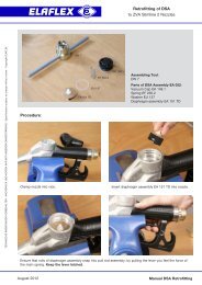
Montagewerkzeug . Assembling Tools1
- Seite 80 und 81:
Beständigkeitsübersicht Armaturen
- Seite 82 und 83:
Sonderausführungen · Special Type
- Seite 84 und 85:
Sonderausführungen . Special Types
- Seite 86 und 87:
Sonderausführungen + Montagewerkze
- Seite 88 und 89:
Montage von SPANNLOC-Klemmbacken .
- Seite 90 und 91:
Sonderausführungen· Special Types
- Seite 92 und 93:
Gebräuchliche Maße für Schlauchf
- Seite 94 und 95:
Sonderausführungen · Special Type
- Seite 97 und 98:
GRUPPE2GE- SCHLAUCH- FLANSCH- FLANS
- Seite 99 und 100:
TECHNISCHE ÄnderunGen VorBehalten
- Seite 101 und 102:
GRUPPEGE-WICHT2 WeightApprox.max.\m
- Seite 103:
Mögliche Längen für ELAFLEX-Schl
- Seite 106 und 107:
Zeichenerklärung| AB. 123 | meistg
- Seite 108 und 109: Sonderausführung · Special TypesD
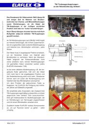
- Seite 110 und 111: DlDie Schemazeichnung zeigt eine EL
- Seite 112 und 113: Kupplungsdichtungen 'KD' für TW-Ku
- Seite 114 und 115: TW Couplings with active Safeguard
- Seite 116 und 117: Problemfälle bei der Kombination v
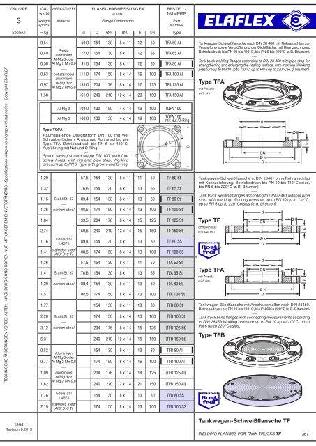
- Seite 119 und 120: GRUPPE Ge· ABMESSUNGEN WERKSTOFFE
- Seite 121 und 122: GRUPPE3 WeightApprox.dAUSFÜHRUNGWE
- Seite 123 und 124: GRUPPEGE-WICHTAUSFÜHRUNGWERKSTOFFE
- Seite 125 und 126: GruppeGewicht3 WeightApprox.Grösse
- Seite 127 und 128: GruppeGewicht3 WeightApprox.Grösse
- Seite 129 und 130: GRUPPEGE-WICHT3 WeightApprox.WERKST
- Seite 131 und 132: GRUPPEGE-WICHT3 WeightApprox.ABMESS
- Seite 133 und 134: GRUPPEGE-WICHT3 WeightApprox.DNGRÖ
- Seite 135 und 136: TECHNISCHE ÄNDERUNGEN VORBEHALTEN
- Seite 137 und 138: TECHNISCHE ÄNDERUNGEN VORBEHALTEN
- Seite 139 und 140: TECHNISCHE ÄNDERUNGEN VORBEHALTEN
- Seite 141 und 142: TECHNISCHE ÄNDERUNGEN VORBEHALTEN
- Seite 143 und 144: GRUPPEGewicht3 WeightApprox.GRÖSSE
- Seite 145 und 146: GRUPPE3WeightApprox.GE- ABMESSUNGEN
- Seite 147 und 148: GRUPPE3WeightApprox.GE- ABMESSUNGEN
- Seite 149 und 150: TECHNISCHE ÄNDERUNGEN VORBEHALTEN
- Seite 151 und 152: GRUPPE3SectionGE- ABMESSUNGEN FORM
- Seite 153 und 154: GRUPPE3GE- ABMESSUNGEN FORM WERKSTO
- Seite 155 und 156: TECHNISCHE ÄNDERUNGEN VORBEHALTEN
- Seite 157: GRUPPE3 WeightApprox.GE- WERKSTOFFE
- Seite 161 und 162: GRUPPE3 WeightApprox.GewichtWERKSTO
- Seite 163 und 164: TECHNISCHE ÄNDERUNGEN VORBEHALTEN
- Seite 165 und 166: TECHNIsche ÄnderunGen Vorbehalten
- Seite 167 und 168: TECHNISCHE ÄNDERUNGEN VORBEHALTEN
- Seite 169 und 170: GRUPPE3SectionGe- VERWENDUNG FÜR A
- Seite 171 und 172: GRUPPE3GE- GRÖSSE WERKSTOFFE1)ABME
- Seite 173 und 174: TECHNISCHE ÄNDERUNGEN VORBEHALTEN
- Seite 175 und 176: Gummi- KompensatorenRubber Expansio
- Seite 177 und 178: GRUPPE4SectionType Innen / Liner Ha
- Seite 179 und 180: SSVSDFlansch Material 3)Flange Mate
- Seite 181 und 182: TECHNISCHE ÄNDERUNGEN VORBEHALTEN
- Seite 183 und 184: TECHNISCHE ÄNDERUNGEN VORBEHALTEN
- Seite 185 und 186: TECHNISCHE ÄNDERUNGEN VORBEHALTEN
- Seite 187 und 188: GRUPPE GEWICHTWirks.fläche4 Weig
- Seite 189 und 190: TECHNISCHE ÄNDERUNGEN VORBEHALTEN
- Seite 191 und 192: GRUPPE4SectionGe- Wirks. BALG PN FL
- Seite 193 und 194: GruppeWirks.Fläche4 Weight Effect.
- Seite 195 und 196: GRUPPE GE- WIRKS.WICHT FLÄCHE4 Wei
- Seite 197 und 198: GruppeWirks.Fläche4 Weight Effect.
- Seite 199 und 200: Gruppe GewichtWirks.fläche4 Weight
- Seite 201 und 202: GRUPPE GE- WIRKS.WICHT FLÄCHE4 Wei
- Seite 203 und 204: GRUPPEGE- Wirks.WICHT Fläche4 Weig
- Seite 205 und 206: GRUPPE4SectionTECHNISCHE ÄNDERUNGE
- Seite 207 und 208: FlanschnormFlange StandardBestellnu
- Seite 209 und 210:
TECHNISCHE ÄNDERUNGEN VORBEHALTEN
- Seite 211 und 212:
Gruppe DN I D Länge L BesteLLnumme
- Seite 213 und 214:
GRUPPE4SectionTECHNISCHE ÄNDERUNGE
- Seite 215 und 216:
GRUPPE4SectionELAFLEX-Gummikompensa
- Seite 217 und 218:
GRUPPE4SectionTECHNISCHE ÄNDERUNGE
- Seite 219 und 220:
Zapfventile+ Zubehör5Fuel Dispensi
- Seite 221 und 222:
TECHNISCHE ÄNDERUNGEN VORBEHALTEN
- Seite 223 und 224:
GRUPPE GE-WICHTWeight5ApproxSCHLAUC
- Seite 225:
GRUPPEGE-WICHT5WeightApproxAUSFÜHR
- Seite 228 und 229:
59677583919910711512360687684921001
- Seite 230 und 231:
25125926727528329129930731525226026
- Seite 232 und 233:
44344444544744844945045145245445545
- Seite 234 und 235:
Ersatzteile, Werkzeuge ZVA Slimline
- Seite 236 und 237:
LeistungskurveZVA Slimline 2 GR----
- Seite 238 und 239:
GE-WICHTWird gebraucht fürZapfsäu
- Seite 240 und 241:
GErsatzteile, Werkzeuge ZVA Slimlin
- Seite 242 und 243:
Leistungsvergleich1,8von ELAFLEX-Au
- Seite 244 und 245:
Beständigkeitsübersicht für ZVA
- Seite 246 und 247:
ELAFLEX REUSABLE PUMP BREAKFIELD RE
- Seite 248 und 249:
AdBlueErsatzteile ZVA Slimline AdBl
- Seite 250 und 251:
GRUPPE3GE- ABMESSUNGEN FORM WERKSTO
- Seite 252 und 253:
Leistungsvergleichvon ELAFLEX Autom
- Seite 254 und 255:
Automatic nozzle ZVA 25 GR :Active
- Seite 256 und 257:
ZVA 32Kugel-Kipp-Ventilsafety cut o
- Seite 258 und 259:
Druckverlustmit Schaugläsern----Pr
- Seite 260 und 261:
Beständigkeitsübersicht für ZV +
- Seite 262 und 263:
Leistungsvergleich0,8von ELAFLEX-Za
- Seite 264 und 265:
Leistungsvergleichvon ELAFLEX-Zapfv
- Seite 266 und 267:
Sonderausführung · Special Type"R
- Seite 268 und 269:
Sonderausführungen · Special Type
- Seite 270 und 271:
Leistungsvergleichvon ELAFLEX-Zapfv
- Seite 272 und 273:
Ersatzteile ZVG 2 · Spare Parts ZV
- Seite 274 und 275:
Druckverlustkurvenfür Flüssiggas-
- Seite 276:
Druckverlustkurvenfür GasGuardFlü
- Seite 279 und 280:
Unsere Historie1923 Gründung durch
- Seite 281 und 282:
Unser ProfilHauptsitz:HamburgMitarb
- Seite 283 und 284:
Marktführer in den BereichenTankst
- Seite 285 und 286:
LPG-Betankung:- Schläuche- Zapfven
- Seite 287 und 288:
Chemische Industrie- Schlauchleitun
- Seite 289 und 290:
Gummi-Kompensatoren(Type ERV)für A
- Seite 291 und 292:
ELAFLEX HIBY,Plettenberg(Herstellun
- Seite 293 und 294:
VertriebsbereicheEHTELAFLEX HIBY Ta
- Seite 295 und 296:
200 autorisierteVertriebspartnerwel
- Seite 297 und 298:
Tank + ChemieschläucheNormgerechte
- Seite 299 und 300:
Normgerecht - Sicher - Langlebig.Ta
- Seite 301:
ZVA Slimline 2 (EN 13012, TRbF 513,