Thermo Scientific TVA-1000B Instruction Manual - Geotech ...
Thermo Scientific TVA-1000B Instruction Manual - Geotech ...
Thermo Scientific TVA-1000B Instruction Manual - Geotech ...
You also want an ePaper? Increase the reach of your titles
YUMPU automatically turns print PDFs into web optimized ePapers that Google loves.
MI 611-185 – June 1996<br />
Hardware<br />
WARNING: To prevent a potential explosion, do not operate the instrument with the<br />
PID or FID detector caps removed.<br />
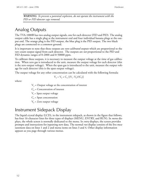
Analog Outputs<br />
The <strong>TVA</strong>-<strong>1000B</strong> has two analog output signals, one for each detector (FID and PID). The analog<br />
output cable has a single plug at the instrument end and four individual banana plugs at the output<br />
end. The orange plug is the FID output, the blue plug is the PID output. The two black<br />
plugs are connected to a common ground.<br />
It is important to note that these outputs are non-calibrated outputs which are proportional to the<br />
raw count output signal from each detector. The outputs are not proportional to the PID and<br />
FID dynamic ranges of 0-2000 and 0-50000 ppm.<br />
To calibrate these outputs, it is necessary to measure the output voltage at the time of gas calibration.<br />
When zero gas is introduced to the unit, measure the output voltage for each detector (this<br />
is the zero output voltage). When the span gas is introduced to the unit, measure the output voltage<br />
for each detector (this is the span output voltage).<br />
The output voltage for any other concentration can be calculated with the following formula:<br />
V x = V o + C x [(V s -V o )/(C s )]<br />
where:<br />
V x = Output voltage at the concentration of interest<br />
C x = Concentration of interest<br />
V s = Span output voltage<br />
C s = Span concentration<br />
V o = Zero output voltage<br />
Instrument Sidepack Display<br />
The liquid crystal display (LCD), in the instrument sidepack, as shown in the figure that follows,<br />
has four 16-character lines for three types of displays (MENU, ENTRY, and RUN). In menu displays,<br />
the whole screen is normally dedicated to the menu. In entry displays, the screen provides<br />
prompts and instructions for inputting new data. The normal run display consists of the live measurement<br />
data on lines 1 and 2 and menu items on lines 3 and 4. Other display information<br />
appears as you page through various menus.<br />
12


