Thermo Scientific TVA-1000B Instruction Manual - Geotech ...
Thermo Scientific TVA-1000B Instruction Manual - Geotech ...
Thermo Scientific TVA-1000B Instruction Manual - Geotech ...

Create successful ePaper yourself
Turn your PDF publications into a flip-book with our unique Google optimized e-Paper software.
Maintenance MI 611-185 – June 1996<br />
8. Turn the end cap over so the red outer surface lies flat and the gray surface faces<br />
up.<br />
9. Place the new flame arrestor in the center hole.<br />
10. Place a screwdriver on the newly installed flame arrestor.<br />
11. Strike the end of the screwdriver with a hammer to secure the new flame arrestor<br />
in place.<br />
12. Replace the spring.<br />
13. Replace the detector cap on the unit.<br />
Cleaning the FID or PID Detector Cavities<br />
1. Close the hydrogen supply valve on the side of the instrument. Turn the instrument<br />
off.<br />
2. Using the special spanner wrench provided with the tool kit, unscrew the cap<br />
holding the respective detector cap.<br />
3. Using the special extractor tool provided with the tool kit, screw the extractor into<br />
the cartridge.<br />
4. Remove the cartridge by pulling on the extractor. Unscrew the extractor from the<br />
cartridge.<br />
5. Carefully clean the inside of the detector cavity using a cotton swab and isopropyl<br />
alcohol. Be sure to clean the high voltage contacts along the side of the cavity. Be<br />
especially careful around the detector signal collector probe at the rear of the cavity<br />
(and the thermocouple probe in the FID).<br />
6. Dry the inside of the cavity using a low heat gun.<br />
7. Insert the cartridges into their respective cavities by reversing the procedure. Note<br />
that the cartridges must be rotated to properly locate the key tabs.<br />
CAUTION: Do not intermix the detector cartridges.<br />
Cleaning or Replacing a Sintered Metal Filter<br />
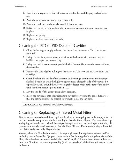
To remove the sintered metal filter cup from the close area sampling assembly, simply unscrew<br />
the cap from the sampler and tip the assembly so that the filter falls out. The same filter cup<br />
and spring are also located behind the sample line quick connect at the sidepack assembly. To<br />
remove, unscrew the quick connect so that the filter falls out. The internal spring will not fall<br />
out. Refer to the assembly diagram below.<br />
You may clean the filter by immersing it in isopropyl alcohol or equivalent solvent and/or<br />
swabbing the surface with a Q-tip or cotton swab. After thoroughly cleaning the surface of the<br />
filter, place the filter in an oven and dry it at 40 °C to 55 °C for one hour. You can then reinsert<br />
the filter into the sampling assembly (with the closed end of the filter in first) and screw<br />
in the cap.<br />
69