1 - The Black Vault
1 - The Black Vault
1 - The Black Vault

You also want an ePaper? Increase the reach of your titles
YUMPU automatically turns print PDFs into web optimized ePapers that Google loves.
PRAETORIAN STARSHIP<br />
any other in the world on TF/TA operations. Educating<br />
USAF operators and maintainers on the<br />
new system proved more challenging. <strong>The</strong> basic<br />
problem with USAF personnel was that the radar<br />
was classified and that operational information<br />
about it was not readily accessible. Flight<br />
crews and maintainers could not easily refer to<br />
the technical orders, thus hindering their ability<br />
to attain vital systems knowledge. In the flying<br />
squadrons, electronic warfare officers kept radar<br />
manuals in their EW safe and signed them out to<br />
pilots and navigators when requested. Because<br />
they were all classified, the manuals could not be<br />
removed from the squadron building, thus preventing<br />
self-study during off-duty periods. An unclassified<br />
article, published by the McDonnell-<br />
Douglas Aircraft Corporation in 1965, discussed<br />
the AN/APQ-99 TF/TA radar installed in the RF-<br />
4 aircraft. <strong>The</strong> article was reproduced and dis -<br />
tributed to pilots and navigators while they were<br />
attending initial Talon training at Pope AFB. As<br />
late as 1968, when the 7th SOS received its four<br />
Combat Talons, the RF-4 article was still con -<br />
sidered the best unclassified document available<br />
on the TF/TA system.<br />
Efforts to declassify the radar and to provide<br />
better information to the Combat Talon community<br />
was realized in 1971, when the annual Combat<br />
Talon Management Review Conference adopted<br />
the first unclassified Lockheed Technical Manual<br />
(LTM) that contained detailed information describing<br />
the TF/TA radar system. <strong>The</strong> description<br />
of radar operations contained in the first LTM<br />
was improved over the years and included in subsequent<br />
LTMs produced for the Combat Talon .<br />
and azimuth, could distinguish between obstacles<br />
located at or above the true horizontal plane of the<br />
aircraft and those located below it. In addition<br />
terrain-following radar (TFR) required a good horizontal<br />
reference for its antenna. Its beam had to accurately<br />
measure the angular aircraft-to-obstacle<br />
relationship in the vertical plane and feed this infor -<br />
mation to a computer, which, in turn, could furnish<br />
necessary climb and dive commands for maintaining<br />
desired vertical-terrain clearances.<br />
<strong>The</strong> TFR employed either the aircraft’s Doppler<br />
system or its inertial navigation system for its antenna’s<br />
primary vertical and horizontal reference.<br />
For the AN/APQ-122(V)B radar, the stabilization<br />
reference could be manually or automatically<br />
switched to the MD-1 gyros if the LN-15J became<br />
unreliable or inoperative. If the Doppler failed<br />
while utilizing the AN/APQ-115, however, the ra -<br />
dar would display a fail indication, and TF opera -<br />
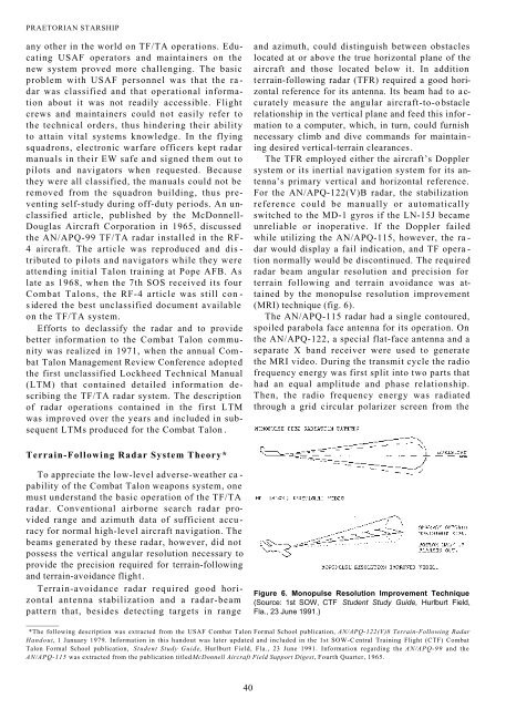
tion normally would be discontinued. <strong>The</strong> required<br />
radar beam angular resolution and precision for<br />
terrain following and terrain avoidance was attained<br />
by the monopulse resolution improvement<br />
(MRI) technique (fig. 6).<br />
<strong>The</strong> AN/APQ-115 radar had a single contoured,<br />
spoiled parabola face antenna for its operation. On<br />
the AN/APQ-122, a special flat-face antenna and a<br />
separate X band receiver were used to generate<br />
the MRI video. During the transmit cycle the radio<br />
frequency energy was first split into two parts that<br />
had an equal amplitude and phase relationship.<br />
<strong>The</strong>n, the radio frequency energy was radiated<br />
through a grid circular polarizer screen from the<br />
'.-jiac-y-iz ni; iiiii!;iTr.^ ririT.<br />
Terrain-Following Radar System <strong>The</strong>ory*<br />
To appreciate the low-level adverse-weather ca -<br />
pability of the Combat Talon weapons system, one<br />
must understand the basic operation of the TF/TA<br />
radar. Conventional airborne search radar provided<br />
range and azimuth data of sufficient accuracy<br />
for normal high-level aircraft navigation. <strong>The</strong><br />
beams generated by these radar, however, did not<br />
possess the vertical angular resolution necessary to<br />
provide the precision required for terrain-following<br />
and terrain-avoidance flight.<br />
Terrain-avoidance radar required good horizontal<br />
antenna stabilization and a radar-beam<br />
pattern that, besides detecting targets in range<br />
I,,... ;^|_.|<br />
Figure 6. Monopulse Resolution Improvement Technique<br />
(Source: 1st SOW, CTF Student Study Guide, Hurlburt Field,<br />
Fla., 23 June 1991.)<br />
__________<br />
*<strong>The</strong> following description was extracted from the USAF Combat Talon Formal School publication, AN/APQ-122(V)8 Terrain-Following Radar<br />
Handout, 1 January 1979. Information in this handout was later updated and included in the 1st SOW-Central Training Flight (CTF) Combat<br />
Talon Formal School publication, Student Study Guide, Hurlburt Field, Fla., 23 June 1991. Information regarding the AN/APQ-99 and the<br />
AN/APQ-115 was extracted from the publication titled McDonnell Aircraft Field Support Digest, Fourth Quarter, 1965.<br />
..:|,;f|<br />
■►^■-■l.' i.h = .hhi.<br />
-.Vl nll.i.L ' -h<br />
V—, -^ j—'-iyii- 01.-.<br />
O<br />
??rO:-LLEL tZ^OLVTi:^ l'=I^.TD '■|D3:.<br />
40


![Combat Support in Korea [270 Pages] - The Black Vault](https://img.yumpu.com/49796461/1/190x71/combat-support-in-korea-270-pages-the-black-vault.jpg?quality=85)