Textos de Apoio (pdf)
Textos de Apoio (pdf)
Textos de Apoio (pdf)

You also want an ePaper? Increase the reach of your titles
YUMPU automatically turns print PDFs into web optimized ePapers that Google loves.
ter may permit such a lower <strong>de</strong>sign rate<br />
of revolution and even, at the same time,<br />
increase the propulsive efficiency.<br />
Propeller coefficients J, K T<br />
and K Q<br />
Propeller theory is based on mo<strong>de</strong>ls,<br />
but to facilitate the general use of this<br />
theory, certain dimensionless propeller<br />
coefficients have been introduced in relation<br />
to the diameter d, the rate of revolution<br />
n, and the water’s mass <strong>de</strong>nsity<br />
. The three most important of these<br />
coefficients are mentioned below.<br />
The advance number of the propeller J<br />
is, as earlier mentioned, a dimensionless<br />
expression of the propeller’s speed of<br />
advance V A<br />
.<br />
VA<br />
J =<br />
n × d<br />
The thrust force T, is expressed<br />
dimensionless, with the help of the<br />
thrust coefficient K T<br />
, as<br />
T<br />
K = T × n × d<br />
and the propeller torque<br />
2 4<br />
Class<br />
S<br />
I<br />
II<br />
III<br />
ISO 484/1 – 1981 (CE)<br />
Manufacturing<br />
accuracy<br />
Very high accuracy<br />
High accuracy<br />
Medium accuracy<br />
Wi<strong>de</strong> tolerances<br />
Mean pitch<br />
for propeller<br />
+/– 0.5 %<br />
+/– 0.75 %<br />
+/– 1.00 %<br />
+/– 3.00 %<br />
Table 5: Manufacturing accuracy classes<br />
of a propeller<br />
Manufacturing accuracy of the propeller<br />
Before the manufacturing of the propeller,<br />
the <strong>de</strong>sired accuracy class standard of<br />
the propeller must be chosen by the<br />
customer. Such a standard is, for example,<br />
ISO 484/1 – 1981 (CE), which<br />
has four different “Accuracy classes”,<br />
see Table 5.<br />
Each of the classes, among other <strong>de</strong>tails,<br />
specifies the maximum allowable<br />
tolerance on the mean <strong>de</strong>sign pitch of<br />
the manufactured propeller, and<br />
thereby the tolerance on the corresponding<br />
propeller speed (rate of revolution).<br />
The price of the propeller, of course,<br />
<strong>de</strong>pends on the selected accuracy<br />
class, with the lowest price for class III.<br />
However, it is not recommen<strong>de</strong>d to<br />
use class III, as this class has a too<br />
high tolerance. This again means that<br />
the mean pitch tolerance should normally<br />
be less than +/– 1.0 %.<br />
The manufacturing accuracy tolerance<br />
corresponds to a propeller speed tolerance<br />
of max. +/– 1.0 %. When also incorporating<br />
the influence of the tolerance<br />
on the wake field of the hull, the total<br />
propeller tolerance on the rate of revolution<br />
can be up to +/– 2.0 %. This tolerance<br />
has also to be borne in mind<br />
when consi<strong>de</strong>ring the operating conditions<br />
of the propeller in heavy weather.<br />
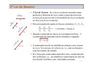
Influence of propeller diameter and<br />
pitch/diameter ratio on propulsive<br />
efficiency D<br />
.<br />
As already mentioned, the highest possible<br />
propulsive efficiency required to<br />
provi<strong>de</strong> a given ship speed is obtained<br />
with the largest possible propeller diameter<br />
d, in combination with the corresponding,<br />
optimum pitch/diameter ratio<br />
p/d.<br />
PD<br />
Q =<br />
2 × n<br />
is expressed dimensionless with the<br />
help of the torque coefficient K Q<br />
, as<br />
Q<br />
K = Q × n × d<br />
2 5<br />
The propeller efficiency O<br />
can be calculated<br />
with the help of the above-mentioned<br />
coefficients, because, as previously<br />
mentioned, the propeller efficiency O<br />
is<br />
<strong>de</strong>fined as:<br />
= P<br />
= T × V<br />
<br />
P × × = K<br />
T<br />
A<br />
T<br />
Q n K<br />
× J<br />
2 2<br />
D<br />
With the help of special and very complicated<br />
propeller diagrams, which<br />
contain, i.a. J, K T<br />
and K Q<br />
curves, it is<br />
possible to find/calculate the propeller’s<br />
dimensions, efficiency, thrust, power, etc.<br />
Q<br />
Shaft power<br />
kW<br />
9,500<br />
9,400<br />
9,300<br />
9,200<br />
9,100<br />
9,000<br />
8,900<br />
8,800<br />
8,700<br />
8,600<br />
8,500<br />
70<br />
p/d<br />
1.00<br />
0.95<br />
80 90<br />
80,000 dwt cru<strong>de</strong> oil tanker<br />
Design draught = 12.2 m<br />
Ship speed = 14.5 kn<br />
d =Propeller diameter<br />
p/d = Pitch/diameter ratio<br />
0.90<br />
7.0 m<br />
0.69<br />
0.85<br />
0.80 7.2 m<br />
0.75 0.70 0.65<br />
d<br />
7.4 m<br />
p/d<br />
0.71<br />
Fig. 9: Propeller <strong>de</strong>sign – influence of diameter and pitch<br />
6.8 m<br />
d<br />
6.6 m p/d<br />
0.67<br />
0.68<br />
0.60<br />
0.55<br />
p/d<br />
0.50<br />
Power and speed curve<br />
for the given propeller<br />
diameter d = 7.2 m with<br />
different p/d<br />
Power and speed curve<br />
for various propeller<br />
diameters d with<br />
optimum p/d<br />
Propeller speed<br />
100 110 120 130 r/min<br />
14
![Conceitos transmissao de dados .Sinais[.pdf]](https://img.yumpu.com/50982145/1/190x146/conceitos-transmissao-de-dados-sinaispdf.jpg?quality=85)
![Packages e interfaces[.pdf]](https://img.yumpu.com/50629553/1/190x134/packages-e-interfacespdf.jpg?quality=85)