Textos de Apoio (pdf)
Textos de Apoio (pdf)
Textos de Apoio (pdf)

Create successful ePaper yourself
Turn your PDF publications into a flip-book with our unique Google optimized e-Paper software.
Electronic governor with load limitation<br />
In or<strong>de</strong>r to safeguard the diesel engine<br />
against thermal and mechanical overload,<br />
the approved electronic governors inclu<strong>de</strong><br />
the following two limiter functions:<br />
• Torque limiter<br />
The purpose of the torque limiter is<br />
to ensure that the limitation lines of<br />
the load diagram are always observed.<br />
The torque limiter algorithm compares<br />
the calculated fuel pump in<strong>de</strong>x (fuel<br />
amount) and the actually measured<br />
engine speed with a reference limiter<br />
curve giving the maximum allowable<br />
fuel pump in<strong>de</strong>x at a given engine<br />
speed. If the calculated fuel pump<br />
in<strong>de</strong>x is above this curve, the resulting<br />
fuel pump in<strong>de</strong>x will be reduced<br />
correspondingly.<br />
The reference limiter curve is to be<br />
adjusted so that it corresponds to the<br />
limitation lines of the load diagram.<br />
• Scavenge air pressure limiter<br />
The purpose of the scavenge air<br />
pressure limiter is to ensure that the<br />
engine is not being overfuelled during<br />
acceleration, as for example during<br />
manoeuvring.<br />
The scavenge air pressure limiter<br />
algorithm compares the calculated<br />
fuel pump in<strong>de</strong>x and measured<br />
scavenge air pressure with a reference<br />
limiter curve giving the maximum<br />
allowable fuel pump in<strong>de</strong>x at a<br />
given scavenge air pressure. If the<br />
calculated fuel pump in<strong>de</strong>x is above<br />
this curve, the resulting fuel pump<br />
in<strong>de</strong>x will be reduced correspondingly.<br />
The reference limiter curve is to be<br />
adjusted to ensure that sufficient air<br />
will always be available for a good<br />
combustion process.<br />
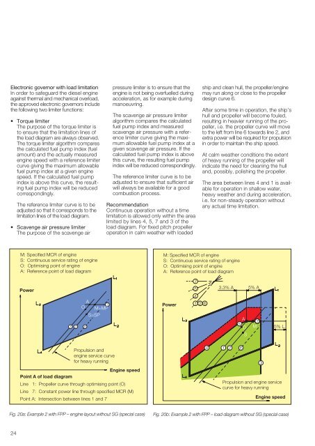
Recommendation<br />
Continuous operation without a time<br />
limitation is allowed only within the area<br />
limited by lines 4, 5, 7 and 3 of the<br />
load diagram. For fixed pitch propeller<br />
operation in calm weather with loa<strong>de</strong>d<br />
ship and clean hull, the propeller/engine<br />
may run along or close to the propeller<br />
<strong>de</strong>sign curve 6.<br />
After some time in operation, the ship’s<br />
hull and propeller will become fouled,<br />
resulting in heavier running of the propeller,<br />
i.e. the propeller curve will move<br />
to the left from line 6 towards line 2, and<br />
extra power will be required for propulsion<br />
in or<strong>de</strong>r to maintain the ship speed.<br />
At calm weather conditions the extent<br />
of heavy running of the propeller will<br />
indicate the need for cleaning the hull<br />
and, possibly, polishing the propeller.<br />
The area between lines 4 and 1 is available<br />
for operation in shallow water,<br />
heavy weather and during acceleration,<br />
i.e. for non-steady operation without<br />
any actual time limitation.<br />
M: Specified MCR of engine<br />
S: Continuous service rating of engine<br />
O: Optimising point of engine<br />
A: Reference point of load diagram<br />
M: Specified MCR of engine<br />
S: Continuous service rating of engine<br />
O: Optimising point of engine<br />
A: Reference point of load diagram<br />
Power<br />
1<br />
2<br />
A<br />
O<br />
6<br />
S=SP<br />
7<br />
M=MP<br />
Power<br />
7<br />
5<br />
4<br />
1 2<br />
6<br />
3.3% A<br />
5% A<br />
A<br />
7<br />
5<br />
O M<br />
S<br />
5% L 1<br />
Propulsion and<br />
engine service curve<br />
for heavy running<br />
Engine speed<br />
Point A of load diagram<br />
Line 1: Propeller curve through optimising point (O)<br />
Line 7: Constant power line through specified MCR (M)<br />
Point A: Intersection between lines 1 and 7<br />
4 1<br />
2<br />
6<br />
Propulsion and engine service<br />
curve for heavy running<br />
3<br />
Engine speed<br />
Fig. 20a: Example 2 with FPP – engine layout without SG (special case)<br />
Fig. 20b: Example 2 with FPP – load diagram without SG (special case)<br />
24
![Conceitos transmissao de dados .Sinais[.pdf]](https://img.yumpu.com/50982145/1/190x146/conceitos-transmissao-de-dados-sinaispdf.jpg?quality=85)
![Packages e interfaces[.pdf]](https://img.yumpu.com/50629553/1/190x134/packages-e-interfacespdf.jpg?quality=85)