Textos de Apoio (pdf)
Textos de Apoio (pdf)
Textos de Apoio (pdf)

You also want an ePaper? Increase the reach of your titles
YUMPU automatically turns print PDFs into web optimized ePapers that Google loves.
charger etc. according to a propeller<br />
curve 1 of the load diagram, equal to<br />
the heavy propeller curve 2.<br />
Instead of point S2, therefore, point SP<br />
will normally be used for the engine layout<br />
by referring this service propulsion<br />
rating to, for example, 90% of the engine’s<br />
specified MCR, which corresponds to<br />
choosing a 10% engine margin.<br />
In other words, in the example the propeller’s<br />
<strong>de</strong>sign curve is about 5% light<br />
running compared with the propeller<br />
curve used for layout of the main engine.<br />
Running in very heavy seas with<br />
heavy waves, point S3<br />
When sailing in very heavy sea against,<br />
with heavy waves, the propeller can be<br />
7-8% heavier running (and even more)<br />
than in calm weather, i.e. at the same<br />
propeller power, the rate of revolution<br />
may be 7-8% lower.<br />
For a propeller power equal to 90% of<br />
specified MCR, point S3 in the load<br />
diagram in Fig. 24 shows an example<br />
of such a running condition.<br />
In some cases in practice with strong<br />
wind against, the heavy running has<br />
proved to be even greater and even to<br />
be found to the left of the limitation line<br />
4 of the load diagram.<br />
In such situations, to avoid slamming of<br />
the ship and thus damage to the stem<br />
and racing of the propeller, the ship<br />
speed will normally be reduced by the<br />
navigating officers on watch.<br />
Ship acceleration and operation in<br />
shallow waters<br />
When the ship accelerates and the<br />
propeller is being subjected to a larger<br />
load than during free sailing, the effect<br />
on the propeller may be similar to that<br />
illustrated by means of point S3 in the<br />
load diagram, Fig. 24. In some cases in<br />
practice, the influence of acceleration<br />
on the heavy running has proved to be<br />
even greater. The same conditions are<br />
valid for running in shallow waters.<br />
Sea running at trial conditions, point S1<br />
Normally, the clean hull propeller curve<br />
6 will be referred to as the trial trip propeller<br />
curve. However, as the ship is<br />
seldom loa<strong>de</strong>d during sea trials and<br />
more often is sailing in ballast, the actual<br />
propeller curve 6.1 will be more<br />
light running than curve 6.<br />
For a power to the propeller equal to<br />
90% specified MCR, point S1 on the<br />
load diagram, in Fig. 24, indicates an<br />
example of such a running condition. In<br />
or<strong>de</strong>r to be able to <strong>de</strong>monstrate operation<br />
at 100% power, if required, during<br />
sea trial conditions, it may in some<br />
cases be necessary to exceed the propeller<br />
speed restriction, line 3, which<br />
during trial conditions may be allowed<br />
to be exten<strong>de</strong>d to 107%, i.e. to line 9<br />
of the load diagram.<br />
S=PD<br />
Line 1<br />
Line 1<br />
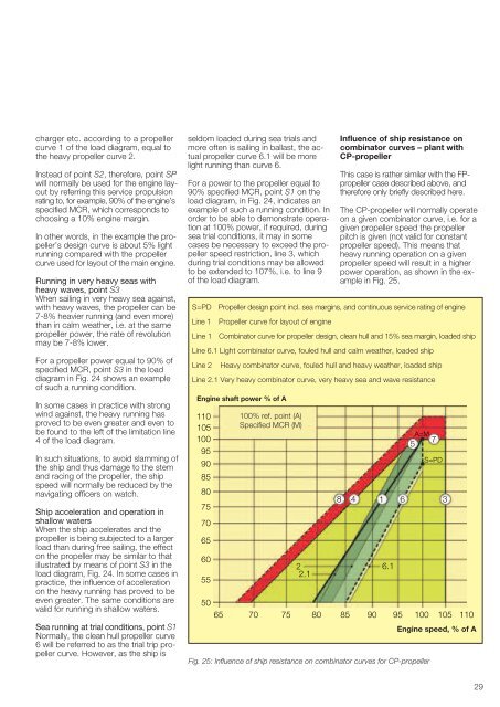
Influence of ship resistance on<br />
combinator curves – plant with<br />
CP-propeller<br />
This case is rather similar with the FPpropeller<br />
case <strong>de</strong>scribed above, and<br />
therefore only briefly <strong>de</strong>scribed here.<br />
The CP-propeller will normally operate<br />
on a given combinator curve, i.e. for a<br />
given propeller speed the propeller<br />
pitch is given (not valid for constant<br />
propeller speed). This means that<br />
heavy running operation on a given<br />
propeller speed will result in a higher<br />
power operation, as shown in the example<br />
in Fig. 25.<br />
Propeller <strong>de</strong>sign point incl. sea margins, and continuous service rating of engine<br />
Propeller curve for layout of engine<br />
Combinator curve for propeller <strong>de</strong>sign, clean hull and 15% sea margin, loa<strong>de</strong>d ship<br />
Line 6.1 Light combinator curve, fouled hull and calm weather, loa<strong>de</strong>d ship<br />
Line 2<br />
Heavy combinator curve, fouled hull and heavy weather, loa<strong>de</strong>d ship<br />
Line 2.1 Very heavy combinator curve, very heavy sea and wave resistance<br />
Engine shaft power % of A<br />
110<br />
105<br />
100<br />
95<br />
90<br />
85<br />
80<br />
75<br />
70<br />
65<br />
60<br />
55<br />
100% ref. point (A)<br />
Specified MCR (M)<br />
2<br />
2.1<br />
A=M<br />
7<br />
5<br />
8 4 1 6 3<br />
50<br />
65 70 75 80 85 90 95 100 105 110<br />
Engine speed, % of A<br />
Fig. 25: Influence of ship resistance on combinator curves for CP-propeller<br />
6.1<br />
S=PD<br />
29
![Conceitos transmissao de dados .Sinais[.pdf]](https://img.yumpu.com/50982145/1/190x146/conceitos-transmissao-de-dados-sinaispdf.jpg?quality=85)
![Packages e interfaces[.pdf]](https://img.yumpu.com/50629553/1/190x134/packages-e-interfacespdf.jpg?quality=85)