

Contents - Volkspage
Contents - Volkspage
Contents - Volkspage

You also want an ePaper? Increase the reach of your titles
YUMPU automatically turns print PDFs into web optimized ePapers that Google loves.
Engine removal and overhaul procedures 2B.11<br />
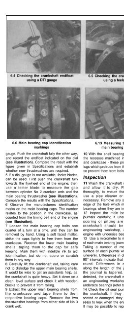
6.4 Checking the crankshaft endfloat<br />
using a DTI gauge<br />
6.5 Checking the crankshaft endfloat<br />
using a feeler blade<br />
the advice of an engineering workshop or your<br />
VW dealer.<br />
15 Measure the crankshaft runout by setting<br />
up a DTI gauge on the centre main bearing<br />
and rotating the shaft in V - blocks. The<br />
maximum deflection of the gauge will indicate<br />
the runout. Take precautions to protect the<br />
bearing journals and oil seal mating surfaces<br />
from damage during this procedure. A<br />
maximum runout figure is not quoted by the<br />
manufacturer, but use the figure of 0.05 mm<br />
as a rough guide. If the runout exceeds this<br />
figure, crankshaft renewal should be<br />
considered - consult your VW dealer or an<br />
engine rebuilding specialist for advice.<br />
16 Refer to Section 8 for details of main and<br />
big-end bearing inspection.<br />
6.6 Main bearing cap identification<br />
markings<br />
gauge. Push the crankshaft fully the other way,<br />
and record the endfloat indicated on the dial<br />
(see illustration). Compare the result with the<br />
figure given in Specifications and establish<br />
whether new thrustwashers are required.<br />
5 If a dial gauge is not available, feeler blades<br />
can be used. First push the crankshaft fully<br />
towards the flywheel end of the engine, then<br />
use a feeler blade to measure the gap<br />
between cylinder No 2 crankpin web and the<br />
main bearing thrustwasher (see illustration).<br />
Compare the results with the Specifications.<br />
6 Observe the manufacturers identification<br />
marks on the main bearing caps. The number<br />
relates to the position in the crankcase, as<br />
counted from the timing belt end of the engine<br />
(see illustration).<br />
7 Loosen the main bearing cap bolts one<br />
quarter of a turn at a time, until they can be<br />
removed by hand. Using a soft faced mallet,<br />
strike the caps lightly to free them from the<br />
crankcase. Recover the lower main bearing<br />
shells, taping them to the cap for safe<br />
keeping. Mark them with indelible ink to aid<br />
identification, but do not score or scratch<br />
them in any way.<br />
8 Carefully lift the crankshaft out, taking care<br />
not to dislodge the upper main bearing shells.<br />
It would be wise to get an assistants help, as<br />
the crankshaft is quite heavy. Set it down on a<br />
clean, level surface and chock it with wooden<br />
blocks to prevent it from rolling.<br />
9 Extract the upper main bearing shells from<br />
the crankcase and tape them to their<br />
respective bearing caps. Remove the two<br />
thrustwasher bearings from either side of No 3<br />
crank web.<br />
6.13 Measuring the diameter<br />
main bearing journals<br />
10 With the shell bearings removed, observe<br />
the recesses machined into the bearing caps<br />
and crankcase - these provide location for the<br />
lugs which protrude from the shell bearings and<br />
so prevent them from being fitted incorrectly.<br />
Inspection<br />
11 Wash the crankshaft in a suitable solvent<br />
and allow it to dry. Flush the oil holes<br />
thoroughly, to ensure that are not blocked -<br />
use a pipe cleaner or a needle brush if<br />
necessary. Remove any sharp edges from the<br />
edge of the hole which may damage the new<br />
bearings when they are installed.<br />
12 Inspect the main bearing and crankpin<br />
journals carefully; if uneven wear, cracking,<br />
scoring or pitting are evident then the<br />
crankshaft should be reground by an<br />
engineering workshop, and refitted to the<br />
engine with undersize bearings.<br />
13 Use a micrometer to measure the diameter<br />
of each main bearing journal (see illustration).<br />
Taking a number of measurements on the<br />
surface of each journal will reveal if it is worn<br />
unevenly. Differences in diameter measured at<br />
90° intervals indicate that the journal is out of<br />
round. Differences in diameter measured<br />
along the length of the journal, indicate that<br />
the journal is tapered. Again, if wear is<br />
detected, the crankshaft must be reground by<br />
an engineering workshop and refitted with<br />
undersize bearings (refer to Reassembly)<br />
14 Check the oil seal journals at either end of<br />
the crankshaft. If they appear excessively<br />
scored or damaged, they may cause the new<br />
seals to leak when the engine is reassembled.<br />
It may be possible to repair the journal; seek<br />
Cleaning<br />
1 Remove all external components and<br />
electrical switches/sensors from the block.<br />
For complete cleaning, the core plugs should<br />
ideally be removed. Drill a small hole in the<br />
plugs, then insert a self-tapping screw into the<br />
hole. Extract the plugs by pulling on the screw<br />
with a pair of grips, or by using a slide<br />
hammer (see illustration).<br />
2 Scrape all traces of gasket and sealant from<br />
the cylinder block/crankcase, taking care not<br />
to damage the sealing surfaces.<br />
3 Remove all oil gallery plugs (where fitted).<br />
The plugs are usually very tight - they may<br />
have to be drilled out, and the holes retapped.<br />
Use new plugs when the engine is<br />
reassembled.<br />
4 If the casting is very dirty, it should be<br />
steam-cleaned. After this, clean all oil holes<br />
and galleries one more time. Flush all internal<br />
passages with water until the water runs clear.<br />
Dry thoroughly, and apply a light film of oil to all<br />
mating surfaces and cylinder bores, to prevent<br />
rusting. If you have access to compressed air,<br />
use it to speed up the drying process, and to<br />
blow out all oil holes and galleries.<br />
A<br />
Warning: Be sure to wear eye<br />
protection when using<br />
! compressed air!<br />
7.1 Using a slide hammer<br />
to remove a core plug<br />
2B


