

Contents - Volkspage
Contents - Volkspage
Contents - Volkspage

You also want an ePaper? Increase the reach of your titles
YUMPU automatically turns print PDFs into web optimized ePapers that Google loves.
2B.12 Engine removal and overhaul procedures<br />
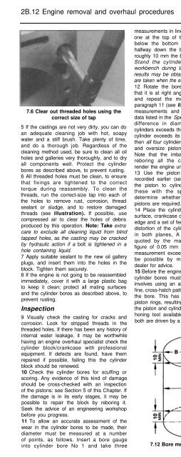
7.6 Clear out threaded holes using the<br />
correct size of tap<br />
5 If the castings are not very dirty, you can do<br />
an adequate cleaning job with hot, soapy<br />
water and a stiff brush. Take plenty of time,<br />
and do a thorough job. Regardless of the<br />
cleaning method used, be sure to clean all oil<br />
holes and galleries very thoroughly, and to dry<br />
all components well. Protect the cylinder<br />
bores as described above, to prevent rusting.<br />
6 All threaded holes must be clean, to ensure<br />
that fixings are tightened to the correct<br />
torque during reassembly. To clean the<br />
threads, run the correct-size tap into each of<br />
the holes to remove rust, corrosion, thread<br />
sealant or sludge, and to restore damaged<br />
threads (see illustration). If possible, use<br />
compressed air to clear the holes of debris<br />
produced by this operation. Note: Take extra<br />
care to exclude all cleaning liquid from blind<br />
tapped holes, as the casting may be cracked<br />
by hydraulic action if a bolt is tightened in a<br />
hole containing liquid.<br />
7 Apply suitable sealant to the new oil gallery<br />
plugs, and insert them into the holes in the<br />
block. Tighten them securely.<br />
8 If the engine is not going to be reassembled<br />
immediately, cover it with a large plastic bag<br />
to keep it clean; protect all mating surfaces<br />
and the cylinder bores as described above, to<br />
prevent rusting.<br />
Inspection<br />
9 Visually check the casting for cracks and<br />
corrosion. Look for stripped threads in the<br />
threaded holes. If there has been any history of<br />
internal water leakage, it may be worthwhile<br />
having an engine overhaul specialist check the<br />
cylinder block/crankcase with professional<br />
equipment. If defects are found, have them<br />
repaired if possible, failing this the cylinder<br />
block should be renewed.<br />
10 Check the cylinder bores for scuffing or<br />
scoring. Any evidence of this kind of damage<br />
should be cross-checked with an inspection<br />
of the pistons: see Section 5 of this Chapter. If<br />
the damage is in its early stages, it may be<br />
possible to repair the block by reboring it.<br />
Seek the advice of an engineering workshop<br />
before you progress.<br />
11 To allow an accurate assessment of the<br />
wear in the cylinder bores to be made, their<br />
diameter must be measured at a number<br />
of points, as follows. Insert a bore gauge<br />
into cylinder bore No 1 and take three<br />
measurements in line with the crankshaft axis;<br />
one at the top of the bore, roughly 10 mm<br />
below the bottom of the wear ridge, one<br />
halfway down the bore and one at a point<br />
roughly 10 mm the bottom of the bore. Note:<br />
Stand the cylinder block squarely on a<br />
workbench during this procedure, inaccurate<br />
results may be obtained if the measurements<br />
are taken when the engine mounted on a stand.<br />
12 Rotate the bore gauge through 90°, so<br />
that it is at right angles to the crankshaft axis<br />
and repeat the measurements detailed in<br />
paragraph 11 (see illustration). Record all six<br />
measurements and compare them with the<br />
data listed in the Specifications Section. If the<br />
difference in diameter between any two<br />
cylinders exceeds the wear limit, or if any one<br />
cylinder exceeds its maximum bore diameter,<br />
then all four cylinders will have to be rebored<br />
and oversize pistons will have to be fitted.<br />
Note that the imbalances produced by not<br />
reboring all the cylinders together would<br />
render the engine unusable.<br />
13 Use the piston diameter measurements<br />
recorded earlier (see Section 5) to calculate<br />
the piston to cylinder clearances. Compare<br />
these with the specified maximum and<br />
determine whether reboring and oversize<br />
pistons are required.<br />
14 Place the cylinder block on a level work<br />
surface, crankcase downwards. Use a straight<br />
edge and a set of feeler blades to measure the<br />
distortion of the cylinder head mating surface<br />
in both planes, A maximum figure is not<br />
quoted by the manufacturer, but use the<br />
figure of 0.05 mm as a rough guide. If the<br />
measurement exceeds this figure, repair may<br />
be possible by machining - consult your<br />
dealer for advice.<br />
15 Before the engine can be reassembled, the<br />
cylinder bores must be honed. This process<br />
involves using an abrasive tool to produce a<br />
fine, cross-hatch pattern on the inner surface of<br />
the bore. This has the effect of seating the<br />
piston rings, resulting in a good seal between<br />
the piston and cylinder. There are two types of<br />
honing tool available to the home mechanic,<br />
both are driven by a rotary power tool, such as<br />
a drill. The ‘Bottle Brush’ hone is a stiff,<br />
cylindrical brush with abrasive stones bonded<br />
to its bristles. The more conventional surfacing<br />
hone has abrasive stones mounted on spring<br />
loaded legs. For the inexperienced home<br />
mechanic, satisfactory results will be achieved<br />
more easily using the Bottle Brush hone. Note:<br />
If you are unwilling to tackle cylinder bore<br />
honing, an engineering workshop will be able to<br />
carry out the job for you at a reasonable cost.<br />
16 Carry out the honing as follows; you will<br />
need one of the honing tools described<br />
above, a power drill/air wrench, a supply of<br />
clean rags, some honing oil and a pair of<br />
safety glasses.<br />
17 Fit the honing tool in the drill chuck.<br />
Lubricate the cylinder bores with honing oil and<br />
insert the honing tool into the first bore,<br />
compressing the stones to allow it to fit. Turn<br />
on the drill at its slowest speed and as the tool<br />
rotates, move it up and down in the bore at a<br />
rate that produces a fine cross-hatch pattern<br />
on the surface. The lines of the pattern should<br />
ideally cross at about 50-60” (see illustration).,<br />
although some piston ring manufacturers may<br />
quote a different angle; check the literature<br />
supplied with the new rings.<br />
A<br />
Warning:<br />
!<br />
Wear safety glasses to<br />
pro tact your eyes from debris<br />
flying off the honing tool.<br />
16 Use plenty of oil during the honing<br />
process. Do not remove any more material<br />
than is necessary to produce the required<br />
finish. When removing the hone tool from the<br />
bore, do not pull it out whilst it is still rotating;<br />
maintain the up/down movement until the<br />
chuck has stopped, then withdraw the tool<br />
whilst rotating the chuck by hand, in the<br />
normal direction of rotation.<br />
19 Wipe out the oil and swarf with a rag and<br />
proceed to the next bore. When all the bores<br />
have been honed, thoroughly clean the whole<br />
cylinder block in hot soapy water to remove<br />
all traces of honing oil and debris. The block<br />
can be considered clean when a clean rag,<br />
moistened with new engine oil does not pick<br />
up any grey residue when wiped along the<br />
bore.<br />
7.12 Bore measurement points 7.17 Cylinder bore honing pattern


