

Contents - Volkspage
Contents - Volkspage
Contents - Volkspage

Create successful ePaper yourself
Turn your PDF publications into a flip-book with our unique Google optimized e-Paper software.
4B.8 Fuel system: multi-point injection models<br />
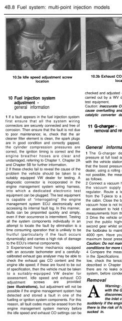
10.3a Idle speed adjustment screw 10.3b Exhaust CO adjustment screw<br />
location<br />
location<br />
10 Fuel injection system<br />
adjustment -<br />
general information<br />
1 If a fault appears in the fuel injection system<br />
first ensure that all the system wiring<br />
connectors are securely connected and free of<br />
corrosion. Then ensure that the fault is not due<br />
to poor maintenance; ie, check that the air<br />
cleaner filter element is clean, the spark plugs<br />
are in good condition and correctly gapped,<br />
the cylinder compression pressures are<br />
correct, the ignition timing is correct and the<br />
engine breather hoses are clear and<br />
undamaged, referring to Chapter 1, Chapter 2A<br />
and Chapter 5B for further information.<br />
2 If these checks fail to reveal the cause of the<br />
problem the vehicle should be taken to a<br />
suitably equipped VW dealer for testing. A<br />
diagnostic connector is incorporated in the<br />
engine management system wiring harness,<br />
into which a dedicated electronic test<br />
equipment can be plugged. The test equipment<br />
is capable of “interrogating” the engine<br />
management system ECU electronically and<br />
accessing its internal fault log. In this manner,<br />
faults can be pinpointed quickly and simply,<br />
even if their occurrence is intermittent. Testing<br />
all the system components individually in an<br />
attempt to locate the fault by elimination is a<br />
time consuming operation that is unlikely to be<br />
fruitful (particularly if the fault occurs<br />
dynamically) and carries a high risk of damage<br />
to the ECU’s internal components.<br />
3 Experienced home mechanics equipped<br />
with an accurate tachometer and a carefullycalibrated<br />
exhaust gas analyser may be able to<br />
check the exhaust gas CO content and the<br />
engine idle speed; if these are found to be out<br />
of specification, then the vehicle must be taken<br />
to a suitably-equipped VW dealer for<br />
assessment. Idle speed and exhaust CO<br />
adjustment screws are provided<br />
(see illustrations), but adjustment will not be<br />
possible if the engine management system has<br />
detected and stored a fault in one of the<br />
fuelling or ignition system components. For this<br />
reason, all fault codes must be erased from the<br />
engine management system memory before<br />
the idle speed and exhaust CO settings can be<br />
checked and adjusted - this operation must be<br />
carried out by a WV dealer with the required<br />
test equipment.<br />
Caution: inaccurate CO adjustment may<br />
cause overfuelling and the risk of serious<br />
catalytic converter damage.<br />
General information<br />
1 The G-charger develops its maximum<br />
pressure at full load and so cannot be tested<br />
with the vehicle stationary. It is recommended<br />
that the boost pressure is measured by a WV<br />
dealer, using a rolling road. However, if this is<br />
not possible, the measurement may be made<br />
as follows.<br />
2 Connect a vacuum hose T-piece in line with<br />
the vacuum supply to the fuel pressure<br />
regulator. Route a length of vacuum hose<br />
from the T-piece to a pressure test gauge in<br />
the cabin. Close the bonnet, ensuring that the<br />
vacuum hose is not trapped. Enlist the help of<br />
an assistant to hold the gauge and read off<br />
measurements from the passenger seat.<br />
3 Drive the vehicle on a strip of private road<br />
(not the public highway) at full throttle in<br />
second gear whilst simultaneously depressing<br />
the footbrake to maintain an engine speed of<br />
4000 rpm. Have your assistant record the<br />
maximum boost pressure indicated.<br />
Caution: Do not maintain these driving<br />
conditions for more than 10 seconds.<br />
4 Compare the measurement with that listed<br />
in the Specifications. If the boost pressure is<br />
low, check the tension of the drivebelts (as<br />
described in Chapter 1) and make sure that<br />
there are no leaks or blockages in the inlet<br />
system, before condemning the G-charger.<br />
Removal<br />
A<br />
Warning: Do not run the engine<br />
with the G-charger air inlet hose<br />
! disconnected; the depression at<br />
the inlet can build up very<br />
suddenly if the engine speed raised and<br />
there is the risk of foreign objects being<br />
sucked in.<br />
10.3c Protective cap (arrowed) fitted to<br />
exhaust CO pre-catalyst sampling pipe<br />
(not fitted to later vehicles)<br />
Caution: Thoroughy clean around all oil pipe<br />
unions before disconnecting them, to<br />
prevent the ingress of dirt. Store<br />
components in a sealed container to prevent<br />
contamination. Cover the G-charger air inlet<br />
ducts to prevent debris entering and clean<br />
using lint-free cloths only.<br />
5 Remove the screws and lift off the<br />
G-charger cover plates.<br />
6 Remove the auxiliary drivebelts (Chapter 1).<br />
7 Slacken the clips and detach the air inlet<br />
and delivery ducting from the G-charger<br />
ports. Cover the open ports with plastic<br />
sheeting secured with elastic bands, to<br />
prevent the ingress of foreign material.<br />
8 Slacken and withdraw the banjo bolts at the<br />
oil supply and return unions. Recover the<br />
sealing washers and discard them - new ones<br />
must be used on refitting. Plug the open<br />
oilways to minimise oil loss and prevent<br />
contamination.<br />
9 Slacken and withdraw the G-charger<br />
mounting bracket bolts, supporting the unit as<br />
the last bolt is withdrawn.<br />
10 Remove the G-charger from the engine<br />
bay together with its mounting bracket and<br />
the drivebelt pulleys.<br />
Refitting<br />
11 Refit the G-charger by following the<br />
removal procedure in reverse, noting the<br />
following points:<br />
a) Ensure that the air inlet ducting is<br />
completely free of debris, before refitting<br />
it and securing the clips.<br />
b) Use new sealing washers when<br />
reconnecting the oil supply and return<br />
unions; tighten the banjo bolts to the<br />
specified torque.<br />
c) With reference to Chapter 1, refit and<br />
tension the auxiliary drivebelts.<br />
12 Unleaded petrol -<br />
general information and usage<br />
Refer to the information in the Specifications<br />
at the start of this Chapter, and in<br />
Chapter 4A.


