

Contents - Volkspage
Contents - Volkspage
Contents - Volkspage

You also want an ePaper? Increase the reach of your titles
YUMPU automatically turns print PDFs into web optimized ePapers that Google loves.
3.6 Cooling, heating and ventilation systems<br />
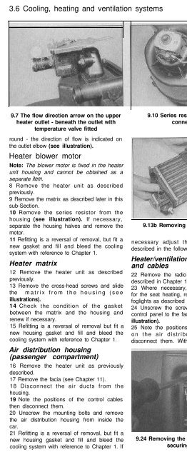
9.7 The flow direction arrow on the upper<br />
heater outlet - beneath the outlet with<br />
temperature valve fitted<br />
round - the direction of flow is indicated on<br />
the outlet elbow (see illustration).<br />
Heater blower motor<br />
Note: The blower motor is fixed in the heater<br />
unit housing and cannot be obtained as a<br />
separate item.<br />
8 Remove the heater unit as described<br />
previously.<br />
9 Remove the matrix as described later in this<br />
sub-Section.<br />
10 Remove the series resistor from the<br />
housing (see illustration). If necessary,<br />
separate the housing halves and remove the<br />
motor.<br />
11 Refitting is a reversal of removal, but fit a<br />
new gasket and fill and bleed the cooling<br />
system with reference to Chapter 1.<br />
Heater matrix<br />
12 Remove the heater unit as described<br />
previously.<br />
13 Remove the cross-head screws and slide<br />
the matrix from the housing (see<br />
illustrations).<br />
14 Check the condition of the gasket<br />
between the matrix and the housing and<br />
renew if necessary.<br />
15 Refitting is a reversal of removal but fit a<br />
new housing gasket and fill and bleed the<br />
cooling system with reference to Chapter 1.<br />
Air distribution housing<br />
(passenger compartment)<br />
16 Remove the heater unit as previously<br />
described.<br />
17 Remove the facia (see Chapter 11).<br />
18 Disconnect the air ducts from the<br />
housing.<br />
19 Note the positions of the control cables<br />
then disconnect them.<br />
20 Unscrew the mounting bolts and remove<br />
the air distribution housing from inside the<br />
car.<br />
21 Refitting is a reversal of removal, but fit a<br />
new housing gasket and fill and bleed the<br />
cooling system with reference to Chapter 1. If<br />
9.10 Series resistor and motor<br />
connections<br />
9.13b Removing the heater matrix<br />
necessary adjust the control cables as<br />
described in the following paragraphs.<br />
Heater/ventilation control panel<br />
and cables<br />
22 Remove the radio and ashtray insert as<br />
described in Chapter 12.<br />
23 Where necessary, remove the switches<br />
for the seat heating, rear window heating and<br />
foglights as described in Chapter 12.<br />
24 Unscrew the screws securing the heater<br />
control panel to the facia and withdraw it (see<br />
illustration).<br />
25 Note the positions of the control cables<br />
on the air distribution housing then<br />
disconnect them. Withdraw the cables from<br />
9.24 Removing the heater control panel<br />
securing screws<br />
9.13a Matrix retaining screw locations in<br />
the heater body<br />
9.13c Heater matrix and temperature<br />
control valve<br />
the facia and if necessary disconnect them<br />
from the controls (see illustration).<br />
26 Refitting is a reversal of removal, but<br />
adjust them as follows.<br />
27 To adjust the regulator valve cable turn<br />
the temperature knob fully anticlockwise to<br />
the “cold” position, then remove the clip<br />
which secures the inner cable to the lever on<br />
the housing. With the outer cable securely<br />
clipped to the housing, move the lever to the<br />
“cold” position then refit the inner cable clip.<br />
28 To adjust the distribution cable turn the<br />
knob fully anticlockwise and remove the outer<br />
cable clip from the housing. Move the housing<br />
lever to the “dash panel outlet” position and<br />
refit the outer cable clip.<br />
9.25 Heater control panel and cable<br />
connections


