

Contents - Volkspage
Contents - Volkspage
Contents - Volkspage

You also want an ePaper? Increase the reach of your titles
YUMPU automatically turns print PDFs into web optimized ePapers that Google loves.
2A.8 Engine in-car repair procedures<br />
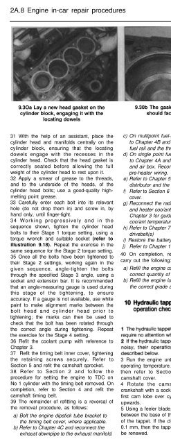
9.3Oa Lay a new head gasket on the<br />
cylinder block, engaging it with the<br />
locating dowels<br />
9.30b The gasket part number<br />
should face upwards<br />
10.6 Hydraulic tappet operation check<br />
31 With the help of an assistant, place the<br />
cylinder head and manifolds centrally on the<br />
cylinder block, ensuring that the locating<br />
dowels engage with the recesses in the<br />
cylinder head. Check that the head gasket is<br />
correctly seated before allowing the full<br />
weight of the cylinder head to rest upon it.<br />
32 Apply a smear of grease to the threads,<br />
and to the underside of the heads, of the<br />
cylinder head bolts; use a good-quality highmelting<br />
point grease.<br />
33 Carefully enter each bolt into its relevant<br />
hole (do not drop them in) and screw in, by<br />
hand only, until finger-tight.<br />
34 Working progressively and in the<br />
sequence shown, tighten the cylinder head<br />
bolts to their Stage 1 torque setting, using a<br />
torque wrench and suitable socket (refer to<br />
illustration 9.18). Repeat the exercise in the<br />
same sequence for the Stage 2 torque setting.<br />
35 Once all the bolts have been tightened to<br />
their Stage 2 settings, working again in the<br />
given sequence, angle-tighten the bolts<br />
through the specified Stage 3 angle, using a<br />
socket and extension bar. It is recommended<br />
that an angle-measuring gauge is used during<br />
this stage of the tightening, to ensure<br />
accuracy. If a gauge is not available, use white<br />
paint to make alignment marks between the<br />
bolt head and cylinder head prior to<br />
tightening; the marks can then be used to<br />
check that the bolt has been rotated through<br />
the correct angle during tightening. Repeat<br />
the exercise for the Stage 4 setting.<br />
36 Refit the coolant pump with reference to<br />
Chapter 3.<br />
37 Refit the timing belt inner cover, tightening<br />
the retaining screws securely. Refer to<br />
Section 5 and refit the camshaft sprocket.<br />
38 Refer to Section 2 and follow the<br />
procedure for setting the engine to TDC on<br />
No 1 cylinder with the timing belt removed. On<br />
completion, refer to Section 4 and refit the<br />
camshaft timing belt.<br />
39 The remainder of refitting is a reversal of<br />
the removal procedure, as follows:<br />
a) Bolt the engine dipstick tube bracket to<br />
the timing belt cover, where applicable.<br />
b) Refer to Chapter 4C and reconnect the<br />
exhaust downpipe to the exhaust manifold.<br />
c) On multipoint fuel-injected systems, refer<br />
to Chapter 4B and refit the fuel injectors,<br />
fuel rail and the throttle body.<br />
d) On single point fuel-injected models, refer<br />
to Chapter 4A and refit the throttle body<br />
and air box. Reconnect the in/et manifold<br />
pre-heater wiring.<br />
e) Refer to Chapter 5B and refit the<br />
distributor and the ignition HT leads.<br />
f) Refer to Section 6 and refit the camshaft<br />
cover.<br />
g) Reconnect the radiator, expansion tank<br />
and heater coo/ant hoses, referring to<br />
Chapter 3 for guidance. Reconnect the<br />
coo/ant temperature sensor wiring.<br />
h) Refer to Chapter 7 and refit the auxiliary<br />
drivebelt(s)<br />
i) Restore the battery connection.<br />
j) Refer to Chapter 11 and refit the bonnet.<br />
40 On completion, refer to Chapter 1 and<br />
carry out the following:<br />
a) Refill the engine cooling system with the<br />
correct quantity of new coolant.<br />
b) Refill the engine lubrication system with<br />
the correct grade and quantity of oil.<br />
3 Run the engine until it reaches its normal<br />
operating temperature. Switch off the engine,<br />
then refer to Section 6 and remove the<br />
camshaft cover.<br />
4 Rotate the camshaft by turning the<br />
crankshaft with a socket and wrench, until the<br />
first cam lobe over cylinder No 1 is pointing<br />
upwards.<br />
5 Using a feeler blade, measure the clearance<br />
between the base of the cam lobe and the top<br />
of the tappet. If the clearance is greater than<br />
0.1 mm, then the tappet is defective and must<br />
be renewed.<br />
6 If the clearance is less than 0.1 mm, press<br />
down on the top of the tappet, until it is felt to<br />
contact the top of the valve stem (see<br />
illustration). Use a wooden or plastic<br />
implement that will not damage the surface of<br />
the tappet.<br />
7 If the tappet travels more than 0.1 mm<br />
before making contact, then it is defective and<br />
must be renewed.<br />
8 Hydraulic tappet removal and refitting is<br />
described as part of the cylinder head<br />
overhaul sequence - see Chapter 2C for<br />
details.<br />
A<br />
Warning:<br />
!<br />
After fitting hydraulic<br />
tappets, wait a minimum of 30<br />
minutes before starting the<br />
engine to allow the tappets time<br />
to settle, otherwise the increased stroke<br />
may cause the pistons to strike the valve<br />
heads.<br />
Removal<br />
1 Disconnect the battery negative cable and<br />
position it away from the terminal.<br />
2 Carry out the following operations:<br />
a) Support the engine and remove the<br />
transmission as described in Chapter 7.<br />
b) Remove the clutch assembly as described<br />
in Chapter 6.<br />
3 Mark the relationship between the flywheel<br />
and the end of the crankshaft with a dab of<br />
paint, to aid refitting later.<br />
4 Hold the flywheel stationary, by means of a<br />
lever or angle iron engaged with the starter<br />
ring gear (refer to Chapter 5A for details of<br />
starter motor removal).<br />
5 Unscrew the bolts progressively and lift the<br />
flywheel from the crankshaft.<br />
Caution: The flywheel is a heavy, bulky<br />
component - enlist the help of an assistant<br />
if possible. Wear gloves to protect your<br />
hands from the ring gear teeth. Discard<br />
the flywheel bolts - new items must be<br />
used on refitting.


