

Contents - Volkspage
Contents - Volkspage
Contents - Volkspage

Create successful ePaper yourself
Turn your PDF publications into a flip-book with our unique Google optimized e-Paper software.
4A.4 Fuel system: single-point injection models<br />
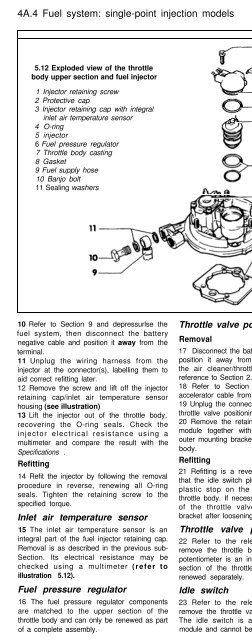
5.12 Exploded view of the throttle<br />
body upper section and fuel injector<br />
1 Injector retaining screw<br />
2 Protective cap<br />
3 Injector retaining cap with integral<br />
inlet air temperature sensor<br />
4 O-ring<br />
5 injector<br />
6 Fuel pressure regulator<br />
7 Throttle body casting<br />
8 Gasket<br />
9 Fuel supply hose<br />
10 Banjo bolt<br />
11 Sealing washers<br />
10 Refer to Section 9 and depressurlse the<br />
fuel system, then disconnect the battery<br />
negative cable and position it away from the<br />
terminal.<br />
11 Unplug the wiring harness from the<br />
injector at the connector(s), labelling them to<br />
aid correct refitting later.<br />
12 Remove the screw and lift off the injector<br />
retaining cap/inlet air temperature sensor<br />
housing (see illustration)<br />
13 Lift the injector out of the throttle body,<br />
recovering the O-ring seals. Check the<br />
injector electrical resistance using a<br />
multimeter and compare the result with the<br />
Specifications .<br />
Refitting<br />
14 Refit the injector by following the removal<br />
procedure in reverse, renewing all O-ring<br />
seals. Tighten the retaining screw to the<br />
specified torque.<br />
Inlet air temperature sensor<br />
15 The inlet air temperature sensor is an<br />
integral part of the fuel injector retaining cap.<br />
Removal is as described in the previous sub-<br />
Section. Its electrical resistance may be<br />
checked using a multimeter (refer to<br />
illustration 5.12).<br />
Fuel pressure regulator<br />
16 The fuel pressure regulator components<br />
are matched to the upper section of the<br />
throttle body and can only be renewed as part<br />
of a complete assembly.<br />
Throttle valve positioning module<br />
Removal<br />
17 Disconnect the battery negative cable and<br />
position it away from the terminal. Remove<br />
the air cleaner/throttle body air box, with<br />
reference to Section 2.<br />
18 Refer to Section 4 and disconnect the<br />
accelerator cable from the throttle body.<br />
19 Unplug the connector from the side of the<br />
throttle valve positioning module.<br />
20 Remove the retaining screws and lift the<br />
module together with the accelerator cable<br />
outer mounting bracket away from the throttle<br />
body.<br />
Refitting<br />
21 Refitting is a reversal of removal. Check<br />
that the idle switch plunger lines up with the<br />
plastic stop on the lower section of the<br />
throttle body. If necessary, adjust the position<br />
of the throttle valve positioning module<br />
bracket after loosening the mounting screws.<br />
Throttle valve potentiometer<br />
22 Refer to the relevant sub-Section and<br />
remove the throttle body. The throttle valve<br />
potentiometer is an integral part of the lower<br />
section of the throttle body and cannot be<br />
renewed separately.<br />
Idle switch<br />
23 Refer to the relevant sub-Section and<br />
remove the throttle valve positioning module.<br />
The idle switch is an integral part of the<br />
module and cannot be renewed separately.<br />
5.30 Two coolant temperature sensors are<br />
fitted; the one colour-coded blue (arrowed)<br />
serves the engine management system<br />
Lambda sensor<br />
Removal<br />
24 The lambda sensor is threaded into the<br />
exhaust pipe, at the front of the catalyst.<br />
25 Disconnect the battery negative cable and<br />
position it away from the terminal, then unplug<br />
the wiring harness from the lambda sensor at<br />
the connector, located at the rear of the<br />
engine, beneath the throttle body.<br />
26 Note: As a flying lead remains connected<br />
to the sensor after is has been disconnected,<br />
if the correct size spanner is not available, a<br />
slotted socket will be required to remove the<br />
sensor. Working under the vehicle, slacken<br />
and withdraw the sensor, taking care to avoid<br />
damaging the sensor probe as it is removed.<br />
Refitting<br />
27 Apply a little anti-seize grease to the<br />
sensor threads - take care to avoid<br />
contaminating the probe tip.<br />
28 Refit the sensor to its housing, tightening<br />
it to the correct torque. Restore the harness<br />
connection.<br />
Coolant temperature sensor<br />
Removal<br />
29 Disconnect the battery negative cable and<br />
position it away from the terminal, then refer<br />
to Chapter 3 and drain approximately one<br />
quarter of the coolant from the engine.<br />
30 The temperature sensor is located on the<br />
left hand side of the cylinder head, under the<br />
heater coolant outlet elbow (see illustration).<br />
There are two sensors fitted; the one colour<br />
coded blue serves the engine management<br />
system, the black one produces a signal for<br />
the instrument panel temperature gauge.<br />
31 Unplug the wiring harness from the sensor<br />
at the connector, then extract the clip and lift<br />
the sensor from its housing, recovering the O-<br />
ring - be prepared for an amount of coolant<br />
loss.<br />
Refitting<br />
32 Refit the sensor by reversing the removal<br />
procedure, using a new O-ring. Refer to<br />
Chapter 1 and top-up the cooling system.


